
Paper box drying equipment for compacting side interior

A technology for drying equipment and cartons, which is applied in the field of carton drying equipment compacted on the opposite side, which can solve the problems of affecting the use of cartons, reducing the stress area, and low strength of cartons, so as to achieve reasonable design, The effect of plump shape and strong function

Active Publication Date: 2020-05-19
兰陵县工程机械配件厂
View PDF6 Cites 0 Cited by
  • Summary
  • Abstract
  • Description
  • Claims
  • Application Information

AI Technical Summary

Problems solved by technology

[0004] In the prior art, when the cardboard is dried, there will be gaps inside while the internal water vapor is evaporated, which will cause the force-bearing area of ​​the internal gaps to become smaller when the cardboard is folded, and the whole carton will easily collapse. , the folded carton has low strength, which affects the use of the carton

Method used


Image

  • Paper box drying equipment for compacting side interior
  • Paper box drying equipment for compacting side interior
  • Paper box drying equipment for compacting side interior

Examples


Embodiment 1

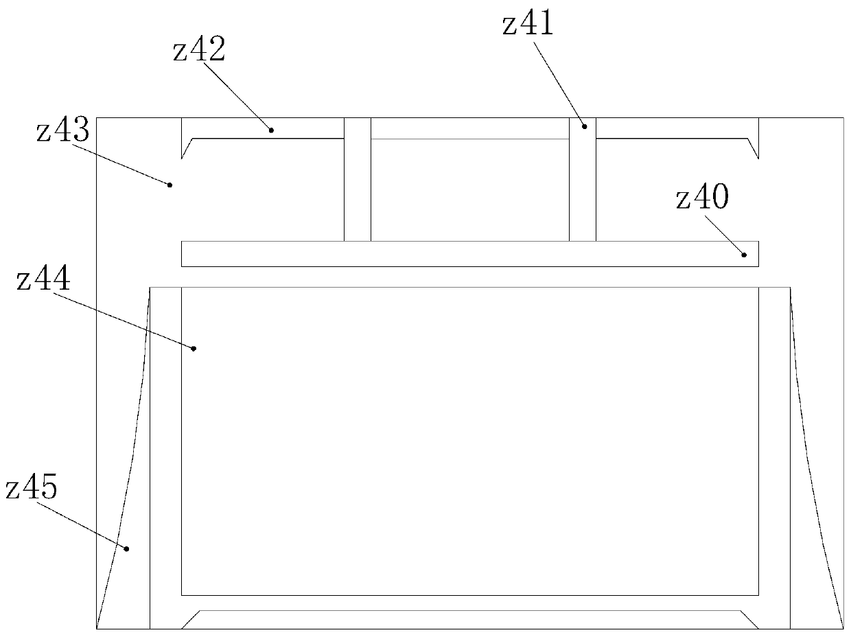
[0028] as attached figure 1 to attach Figure 5 As shown, the present invention provides a carton drying equipment compacted on the opposite side, its structure includes a sealing door z1, a conversion heat cylinder z2, a shifting frame z3, a drying heat box z4, and a distance adjustment head z5. The sealing door z1 is hinged on the right side of the drying heat box z4, the conversion heat cylinder z2 is provided with four and vertically welded on the top of the drying heat box z4, and the shift frame z3 is locked on the conversion heat tank by rivets. The two sides of the heat cylinder z2 are slidingly connected with the top of the drying heat box z4. The distance adjustment head z5 is mechanically connected to the left side of the shifting frame z3. The drying heat box z4 is composed of an attached guide plate z40, Vertical guide column z41, encapsulation bag z42, sealing box z43, heat drying box z44, heat wrapping pad z45, the encapsulation bag z42 passes through the top i...

Embodiment 2

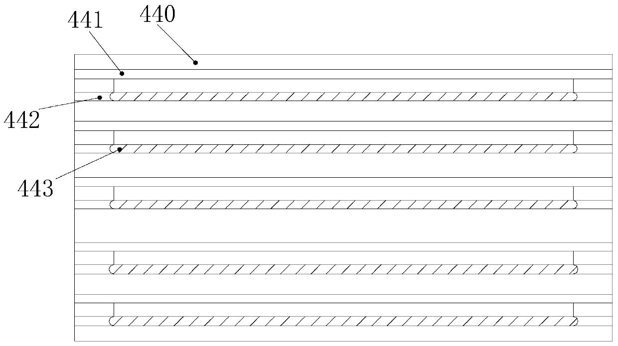
[0032] On the basis of embodiment 1, as attached Figure 6 As shown in appendix 7, the present invention provides a carton drying equipment compacted on the opposite side. The heat wrapping pad z45 is composed of a buckle chuck 450, a parallel arm 451, and a joint longitudinal bar 452. The joint longitudinal bar 452 is welded together with the bottom of the inside of the sealed box z43. The parallel arm 451 is provided with two vertical nails connected to the left and right ends of the longitudinal bar 452. The buckle chuck 450 is hinged inside the parallel arm 451, each A buckle chuck 450 corresponds to the side of each cardboard to improve the edge closing effect of the cardboard edge. The buckle chuck 450 is composed of an inner pressure plate 500, a shrinking sheet 600, a shrinking ball 700, and a clamping frame 800. The inner shrinking The ball 700 is hinged inside the side-by-side arm 451, the shrinking piece 600 is mechanically connected to the upper and lower ends of t...


PUM


Abstract

The invention discloses paper box drying equipment for compacting the side interior. The paper box drying equipment structurally comprises a sealing door, conversion heat barrels, a displacement frame, a drying heat box and a distance adjusting head. The sealing door is hinged to the right side of the drying heat box. The four conversion heat barrels are arranged and vertically welded to the upperportion of the drying heat box and are arranged on the left side and the right side of a paper board correspondingly. A bottommost head end column is started and drives a bottom end column and a self-adaptation column to start to roll on the paper board, when the bottom end column and the self-adaptation column roll to the center, the bottom end column and the self-adaptation column can be contracted into the head end column, the two ends are staggered for rolling again, in the rolling process, an expanding groove can dry the paper board, grinding points can compress the paper board, the paper board can be compressed while being dried, the interior gap is fully filled when the water is evaporated to dryness, the paper board integrally becomes more compact, and after the paper board is folded into a paper box, more durability is achieved.

Description

technical field [0001] The invention relates to a carton drying device, in particular to a carton drying device with inner compaction on opposite sides. Background technique [0002] Cartons are widely used in packaging, industry, transportation, etc. The raw materials can be pure cardboard, composite boards with metal ions, or waterproof materials. Cartons are made by folding cardboard. As a result, the cardboard needs to be dried before folding to ensure the stability of the carton after folding. When drying the cardboard, a method similar to aeration is generally used, and the cardboard is placed in a hot air box for drying. [0003] Based on the above description, the inventors found that the existing carton drying equipment compacted on the opposite side mainly has the following deficiencies, such as: [0004] In the prior art, when the cardboard is dried, there will be gaps inside while the internal water vapor is evaporated, which will cause the force-bearing area of...

Claims


Application Information

Patent Timeline
Patent Type & Authority Applications(China)
IPC IPC(8): F26B9/06F26B21/00F26B25/00
CPCF26B9/066F26B21/001F26B21/004F26B25/00
Inventor 石庆东
Owner 兰陵县工程机械配件厂
Learn More