
Water and sand energy storage power generation system

A technology of energy storage for power generation and water and sand, which is applied in hydropower, hydropower stations, water conservancy projects, etc., and can solve problems such as mismatching of load characteristics, pollution, downstream ecological damage, etc.

Active Publication Date: 2020-05-19
INST OF ELECTRICAL ENG CHINESE ACAD OF SCI
View PDF6 Cites 0 Cited by
  • Summary
  • Abstract
  • Description
  • Claims
  • Application Information

AI Technical Summary

Problems solved by technology

[0007] The purpose of this invention is to propose a water-sand energy storage power generation system to solve the problems of large fluctuations in new energy power generation and mismatched load characteristics in water-poor areas, and at the same time avoid downstream ecological damage and chemical damage caused by the construction of pumped storage power stations. Pollution from post-processing of energy storage, etc.

Method used


Image

  • Water and sand energy storage power generation system
  • Water and sand energy storage power generation system
  • Water and sand energy storage power generation system

Examples


Embodiment Construction

[0043] The present invention will be further described below in conjunction with the accompanying drawings and specific embodiments.

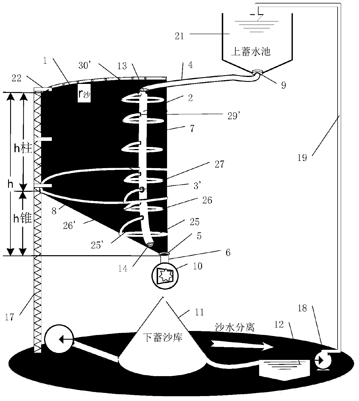
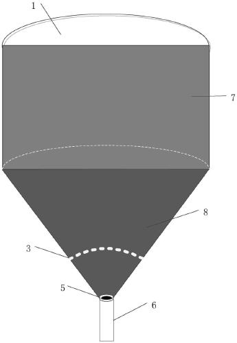
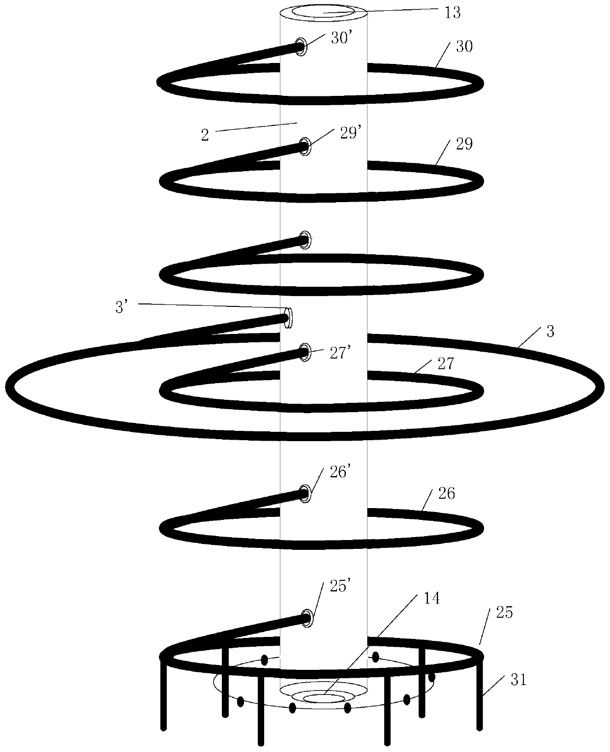
[0044] Such as figure 1 and figure 2 As shown, the water-sand energy storage power generation system of the present invention is composed of an upper sand storage 1, a lower sand storage 11, an upper storage tank 21, a lower storage tank 12, a water-like turbine 10, a water pump 18 and a transmission unit. The upper sand storage 1 and the upper storage tank 21 are located at the upper part of the water-sand storage power generation system, and the lower sand storage 11, the lower storage tank 12 and the water pump 18 are located at the bottom of the water-sand storage power generation system; 10 is installed between the upper sand storage 1 and the lower sand storage 11; the transmission unit is located at one side of the water-sand energy storage power generation system.

[0045] Described upper reservoir 21 is built on one side of upper sa...


PUM


Abstract

The invention discloses a water and sand energy storage power generation system. The system is characterized in that an upper sand storage warehouse (1) and an upper water storage pond (21) of the system are located on the upper portion of the water and sand energy storage power generation system, and a lower sand storage warehouse (11), a lower water storage pond (12) and a water pump (18) are located on the lower portion of the water and sand energy storage power generation system; a similar water turbine (10) is mounted between the upper sand storage warehouse (1) and the lower sand storagewarehouse (11); a conveying unit is located on one side of the water and sand energy storage power generation system; the bottom of the upper water storage pond (21) is higher than the top of the upper sand storage warehouse (1); and the lower water storage pond (12) is lower than the bottom horizontal plane of the lower sand storage warehouse (11). The water and sand energy storage power generation system is built by utilizing mountains, sand gravity is decomposed by utilizing a granary effect, the bottom load of the upper sand storage warehouse is reduced, and viscous resistance during sandflowing is overcome under the action of water by utilizing the gravitational potential energy of sand, so that sand and water potential energy is converted into kinetic energy to act to drive the similar water turbine to generate power, falling sand and water are separated through terrain, and sand lifting and water pumping energy storage are conducted when surplus electricity exists.

Description

technical field [0001] The invention relates to an energy storage power station. Background technique [0002] It is well known that the uncertainty and instability of photovoltaic and wind power generation cause fluctuations in the power grid, resulting in large-scale curtailment of wind and light, and huge losses for large-scale power plants, especially in Northwest China. Pumped hydro storage, compressed air energy storage, and chemical energy storage are good solutions. Pumped storage has the characteristics of high power and long discharge time, and the efficiency is between 60% and 70%. At present, the largest pumped storage power station in operation in the world is Basconti pumped storage in Virginia, USA. Power station with a capacity of 3 gigawatts and a maximum power generation time of 10 hours and 18 minutes. The pumped storage power station is an important adjustment tool for the power system. It has the advantages of flexible startup and fast adjustment. It i...

Claims


Application Information

Patent Timeline
Patent Type & Authority Applications(China)
IPC IPC(8): F03B13/06E02B9/00B65G37/00
CPCB65G37/00B65G2201/045E02B9/00F03B13/06Y02E10/20Y02E60/16Y02P70/10
Inventor 杨子龙王哲雷鸣宇陈卓黄欣科王一波
Owner INST OF ELECTRICAL ENG CHINESE ACAD OF SCI
Learn More