
Bioreactor

A technology of bioreactor and reaction tank, which is applied in the direction of bioreactor/fermenter combination, specific-purpose bioreactor/fermenter, biochemical instrument, etc. and other problems, to achieve the effect of reducing death due to hypoxia, increasing reaction yield, and wide distribution of oxygen

Inactive Publication Date: 2020-05-19
杨冬生
View PDF0 Cites 2 Cited by
  • Summary
  • Abstract
  • Description
  • Claims
  • Application Information

AI Technical Summary

Problems solved by technology

[0005] In view of the deficiencies in the prior art, the purpose of the present invention is to provide a bioreactor to solve the problem of the prior art because the organisms reacted in the container have a higher density and denser growth, so more oxygen is needed, directly Passing into the culture medium or container will cause oxygen to diffuse slowly, make the amount of oxygen obtained by the organism uneven, cause some organisms to die due to hypoxia, and then affect the reaction effect of the organism and reduce the problem of reaction yield.

Method used


Image

  • Bioreactor
  • Bioreactor
  • Bioreactor

Examples


Embodiment 1

[0032] Example 1: Please refer to Figure 1-Figure 10 , the specific embodiments of the present invention are as follows:

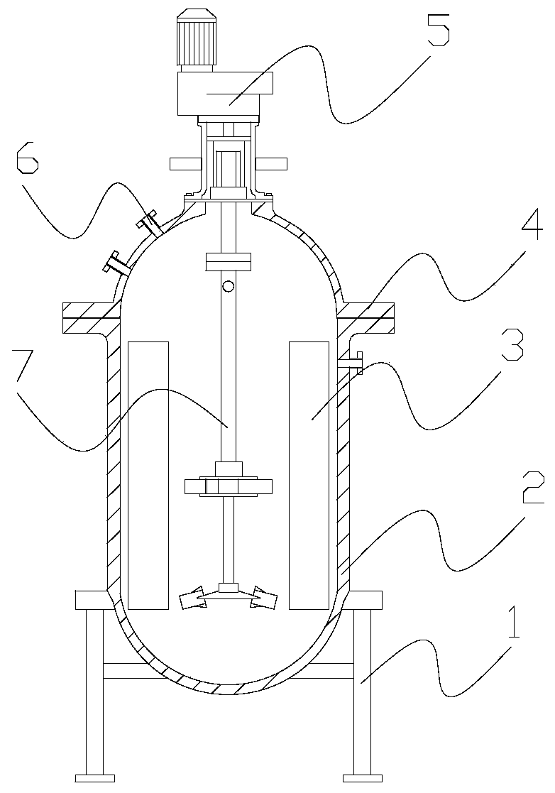
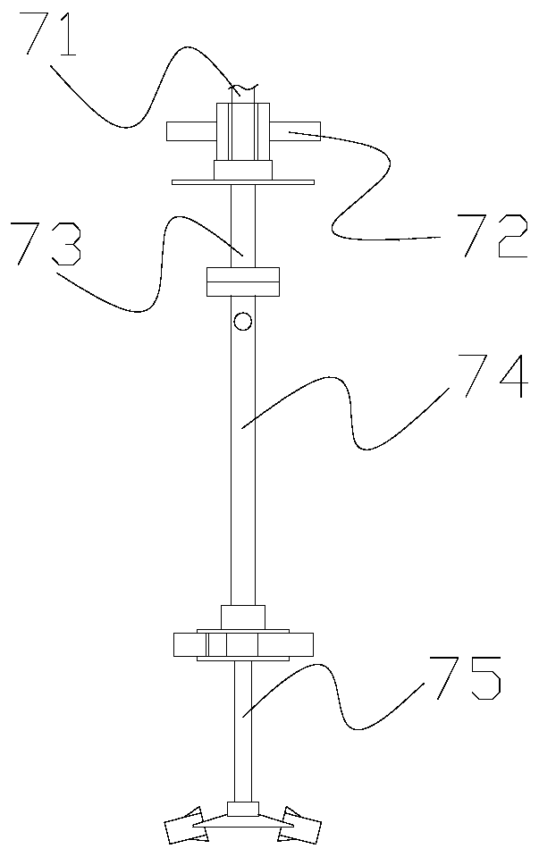
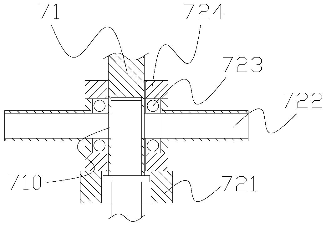
[0033] Its structure includes a chassis 1, a reaction tank 2, a heat exchange plate 3, a tank cover 4, a drive box 5, a feed inlet 6, and an aeration mixing structure 7. The reaction tank 2 is vertically installed on the upper end of the chassis 1 and is relatively Welding, the heat exchange plate 3 is embedded and installed inside the reaction tank 2, the tank cover 4 is installed horizontally on the upper end of the reaction tank 2 and is mechanically connected, and the drive box 5 runs through the upper end of the tank cover 4 and the aeration mixing structure 7 The upper end is connected, and the feed inlet 6 is installed on the outside of the tank cover 4 and communicated with the inside of the reaction tank 2; the aeration mixing structure 7 includes a main shaft 71, an air intake structure 72, a connecting pipe 73, a rotating rod 74, a mixing Stru...

Embodiment 2

[0041] Example 2: Please refer to Figure 9-Figure 12 , the specific embodiments of the present invention are as follows:

[0042] The gas mixing structure 754 includes a connection sleeve 54a, a communication structure 54b, and a gas mixing plate 54c. The connection sleeve 54a is horizontally installed on the upper end of the communication structure 54b and is located on the same axis. The gas mixing plate 54c is installed on the outside of the communication structure 54b And the inside is connected.

[0043] refer to Figure 11 , the communication structure 54b includes a body b1, a port b2, an upper communication port b3, and an inner cavity b4, the port b2 runs through the inside of the body b1, and the upper communication port b3 is located at the upper end of the body b1 and is an integrated structure , the inner chamber b4 is located inside the body b1 and communicates with the port b2 and the upper communication port b3 respectively, the gas can pass into the inner c...


PUM


Abstract

The invention discloses a bioreactor. The structure of the bioreactor comprises a base frame, a reaction tank, a heat exchange plate, a tank cover, a driving box, a feeding port and a gas-increasing mixing structure. The reaction tank is vertically installed on the upper end of the base frame, the heat exchange plate is embedded and installed in the inner side of the reaction tank, the tank coveris horizontally installed on the upper end of the reaction tank, the driving box penetrates the upper end of the tank cover, the feeding port is installed on the outer side of the tank cover, the gas-increasing mixing structure comprises a main shaft, a gas-intake structure, a communication pipe, a rotating rod and a mixing structure, the main shaft is vertically installed at the upper end of thegas-intake structure, the communication pipe is installed at the lower end of the gas-intake structure, the rotating rod is mechanically connected to the lower end of the communication pipe, and the mixing structure is installed at the lower end of the rotating rod. According to the present invention, the lower end of the driving box is provided with the gas-increasing mixing structure, which helps the diffusion of oxygen, so that organisms obtain oxygen better, and the death of organisms caused by hypoxia is reduced; and the lower end of the communication pipe is provided with a gas-mixing structure, so that oxygen in the culture medium is more widely distributed, the biological reaction is better carried out, and the reaction yield is improved.

Description

technical field [0001] The invention belongs to the field of biological reactions, and in particular relates to a bioreactor. Background technique [0002] Biological reaction refers to the use of the biological function of the organism itself to react to produce the desired target product, thereby simulating the growth environment of the organism in the container to cultivate the product, so it is necessary to use such a bioreactor Containers are used to react organisms. In order to increase the output of target products, more organisms need to be put into them for reaction, but the prior art has the following disadvantages: [0003] Due to the high density of the organisms reacting in the container, the growth is relatively dense, and more oxygen is needed. Directly passing into the culture medium or the container will cause the oxygen to diffuse slowly and make the amount of oxygen obtained by the organisms uneven. , causing some organisms to die due to hypoxia, which in...

Claims


Application Information

Patent Timeline
Patent Type & Authority Applications(China)
IPC IPC(8): C12M1/00C12M1/06C12M1/02
CPCC12M23/02C12M23/38C12M23/48C12M27/04C12M41/22
Inventor 杨冬生
Owner 杨冬生
Learn More