
A method, device and computer storage medium for generating a tracking path

A path and sub-path technology, applied in computing, 3D image processing, image data processing, etc., can solve the problems of blindness in generating paths, low algorithm efficiency, and reduced rendering effects, so as to improve computing processing efficiency and avoid blindness. Effect

Active Publication Date: 2020-06-30
西安芯云半导体技术有限公司
View PDF7 Cites 0 Cited by
  • Summary
  • Abstract
  • Description
  • Claims
  • Application Information

AI Technical Summary

Problems solved by technology

The above examples and other conventional path-tracing-based rendering schemes all have a common shortcoming during the implementation process, that is, in the process of generating the tracing path, due to the randomness of the Markov transition probability corresponding to each step of the ray, thus Causes the blindness of the generated path, resulting in a large number of emitted rays that cannot travel within the specified number of random walks In addition, it is difficult to find the path between the viewpoint and the light source in some situations where the viewpoint position or the light source position is relatively hidden, resulting in a large number of noise points, which greatly reduces the rendering effect

Method used


Image

  • A method, device and computer storage medium for generating a tracking path
  • A method, device and computer storage medium for generating a tracking path
  • A method, device and computer storage medium for generating a tracking path

Examples


Embodiment Construction

[0047] The following will clearly and completely describe the technical solutions in the embodiments of the present invention with reference to the drawings in the embodiments of the present invention.

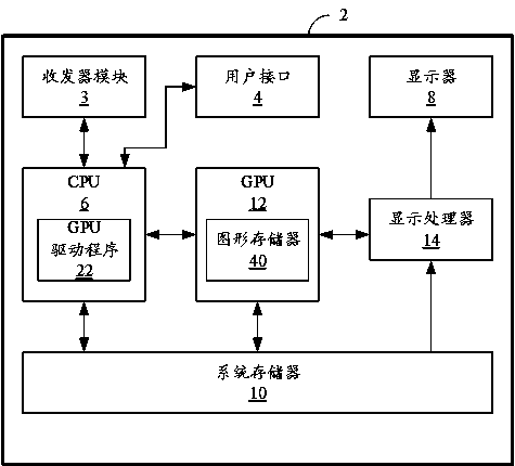
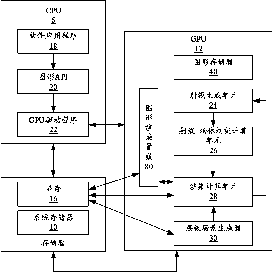
[0048] figure 1A computing device 2 is provided for embodiments of the present invention. Examples of the computing device 2 include, but are not limited to: wireless devices, mobile or cellular telephones (including so-called smart phones), personal digital assistants (PDAs), video game consoles (including video displays, mobile video game devices, mobile video conferencing units), laptop computers, desktop computers, television set-top boxes, tablet computing devices, e-book readers, fixed or mobile media players, etc. exist figure 1 In an example, the computing device 2 may include: a processor 6 , a system memory 10 and a GPU 12 . Computing device 2 may also include display processor 14 , transceiver module 3 , user interface 4 , and display 8 . Both transceiver module ...


PUM


Abstract

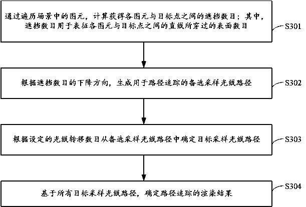
The embodiment of the present invention discloses a method, device, and computer storage medium for generating a tracking path; the method may include: calculating and obtaining the number of occlusions between each graphic element and a target point by traversing the graphic elements in the scene; wherein, the The occlusion number is used to characterize the number of surfaces passed by the straight line between each of the primitives and the target point; according to the descending direction of the occlusion number, an alternative sampling ray path for path tracing is generated; according to the set ray transfer The number of target sampled ray paths is determined from the candidate sampled ray paths; based on all target sampled ray paths, the rendering result of the path tracing is determined.

Description

technical field [0001] Embodiments of the present invention relate to the technical field of Graphics Processing Unit (GPU), and in particular, to a method, device and computer storage medium for generating a tracking path. Background technique [0002] Three-dimensional (3D) rendering can refer to an image processing process that synthesizes data from a 3D object into an image observed at a given viewpoint of a camera, while as an example of a rendering method, ray tracing techniques can involve tracing the An incident light path that emits light rays toward each pixel of an image to generate an image. For a GPU chip that has both ray tracing and conventional graphics rendering pipeline functions, the ray tracing rendering pipeline is usually logically separated from the conventional graphics rendering pipeline. For the case where the GPU uses ray tracing rendering and global illumination needs to be rendered, the path tracing rendering method is a common solution. [000...

Claims


Application Information

Patent Timeline
Patent Type & Authority Patents(China)
IPC IPC(8): G06T15/06
CPCG06T15/06
Inventor 李亮张竞丹樊良辉李洋刘奔
Owner 西安芯云半导体技术有限公司
Learn More