
A new type of detachable temperature controller for power cabinet

A technology of temperature controller and power cabinet, which is applied in the direction of using electric means for temperature control, board/panel/desk of substation/switchgear, etc., can solve the problems of inability to disassemble and difficult to disassemble the thermostat, and improve the stability , The effect of card installation is stable

Active Publication Date: 2021-05-14
PANJIN GUANGLIDA ELECTRIC
View PDF10 Cites 0 Cited by
  • Summary
  • Abstract
  • Description
  • Claims
  • Application Information

AI Technical Summary

Problems solved by technology

[0003] The thermostats of existing power cabinets generally adopt a mosaic structure. Although the mosaic installation structure is firmly connected and the cost is low, when the thermostat is damaged, it will be difficult to disassemble the thermostat or even impossible. disassembly problem

Method used


Image

  • A new type of detachable temperature controller for power cabinet
  • A new type of detachable temperature controller for power cabinet
  • A new type of detachable temperature controller for power cabinet

Examples


Embodiment 1

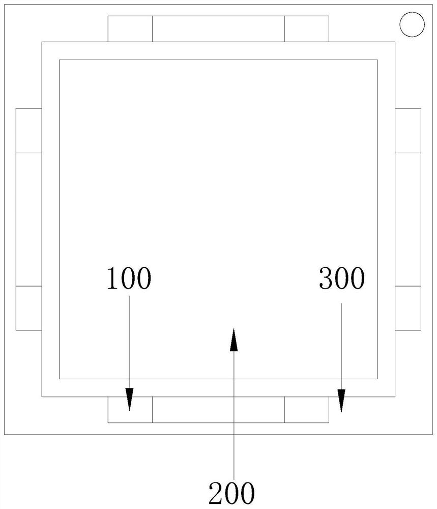
[0030] see Figure 1-5 , the present invention provides a technical solution for a new type of detachable temperature controller for power cabinets: its structure includes a guide installation strip 100, a detachable temperature controller 200, and an embedded installation frame 300. The detachable temperature controller 200 Guide installation strips 100 are fixed at both ends of the four sides, the detachable temperature controller 200 is set in the embedded installation frame 300, and the guide installation strips 100 are connected with the embedded installation frame 300;

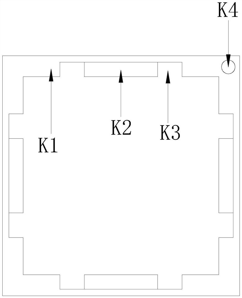
[0031] The embedded installation frame 300 includes a frame body K1, a mounting seat K2, a rectangular groove K3, and a power-on button K4. The four inner positions of the frame body K1 are all provided with a rectangular groove K3, and the rectangular groove K3 is in the middle position. There are four installation seats K2 connected in series to the power-on button K4, the installation seats K2 are fix...

Embodiment 2

[0043] see Figure 1-7 , the present invention provides a technical solution for a new type of detachable temperature controller for power cabinets: its structure includes a guide installation strip 100, a detachable temperature controller 200, and an embedded installation frame 300. The detachable temperature controller 200 Guide installation strips 100 are fixed at both ends of the four sides, the detachable temperature controller 200 is set in the embedded installation frame 300, and the guide installation strips 100 are connected with the embedded installation frame 300;

[0044] The embedded installation frame 300 includes a frame body K1, a mounting seat K2, a rectangular groove K3, and a power-on button K4. The four inner positions of the frame body K1 are all provided with a rectangular groove K3, and the rectangular groove K3 is in the middle position. There are four installation seats K2 connected in series to the power-on button K4, the installation seats K2 are fix...


PUM


Abstract

The invention discloses a new detachable temperature controller for a power cabinet. Its structure includes guide installation strips, a detachable temperature controller, and an embedded installation frame. The installation strip, the detachable temperature controller is set in the embedded installation frame. Compared with the prior art, the beneficial effect of the present invention is that the detachable temperature controller is indirectly installed with the power cabinet through the embedded installation frame. When the temperature controller is damaged, the temperature controller can be disassembled for maintenance, and the installation of the detachable temperature controller and the embedded installation frame is clamped by using the elasticity of the spring in four positive directions. The clamping is more stable, and the spring in the clamping It is in the original position, which can prevent the deformation of the spring. Before installation, the magnet is energized to generate magnetism. Based on the principle of magnetism, the card beads are kept away from it for easy insertion. normal use of the controller.

Description

technical field [0001] The invention relates to the technical field of temperature instruments and meters, in particular to a new detachable temperature controller for a power cabinet. Background technique [0002] The temperature controller is an intelligent temperature control instrument with integrated regulation and control. It adopts a fully digital integrated design. It automatically samples and monitors the ambient temperature through a temperature sensor. When the ambient temperature is higher than the control set value, the control circuit starts, and the control can be set. Hysteresis, with programmable temperature curve or fixed-point constant temperature control, alarm switch output, real-time data query and other functions. [0003] The thermostats of the existing power cabinets generally adopt a mosaic structure. Although the mosaic installation structure is firmly connected and the cost is low, when the thermostat is damaged, it will be difficult to disassembl...

Claims


Application Information

Patent Timeline
Patent Type & Authority Patents(China)
IPC IPC(8): G05D23/19H02B1/04
CPCG05D23/19H02B1/04
Inventor 许春俤
Owner PANJIN GUANGLIDA ELECTRIC
Learn More