
CAN bus simulation monitoring system

A CAN bus, analog monitoring technology, applied in the direction of test/monitoring control system, general control system, control/regulation system, etc., can solve the problem of poor real-time performance of CAN communication module or CAN card, insufficient trigger control data sending and receiving function, and data shielding reception Insufficient functions and other problems, to improve adaptability, increase trigger control data sending and receiving, and meet the needs of use

Active Publication Date: 2020-05-15
北京京航计算通讯研究所
View PDF8 Cites 1 Cited by
  • Summary
  • Abstract
  • Description
  • Claims
  • Application Information

AI Technical Summary

Problems solved by technology

[0009] The technical problem to be solved in the present invention is: solve the problems such as poor real-time performance of the current CAN communication module or CAN card, insufficient function of sending and receiving trigger control data, lack of regular sending function, insufficient function of data shielding reception, etc., improve its function, and improve the CAN bus in different Adaptability in industrial applications to meet various usage needs

Method used


Image

  • CAN bus simulation monitoring system
  • CAN bus simulation monitoring system
  • CAN bus simulation monitoring system

Examples


Embodiment 1

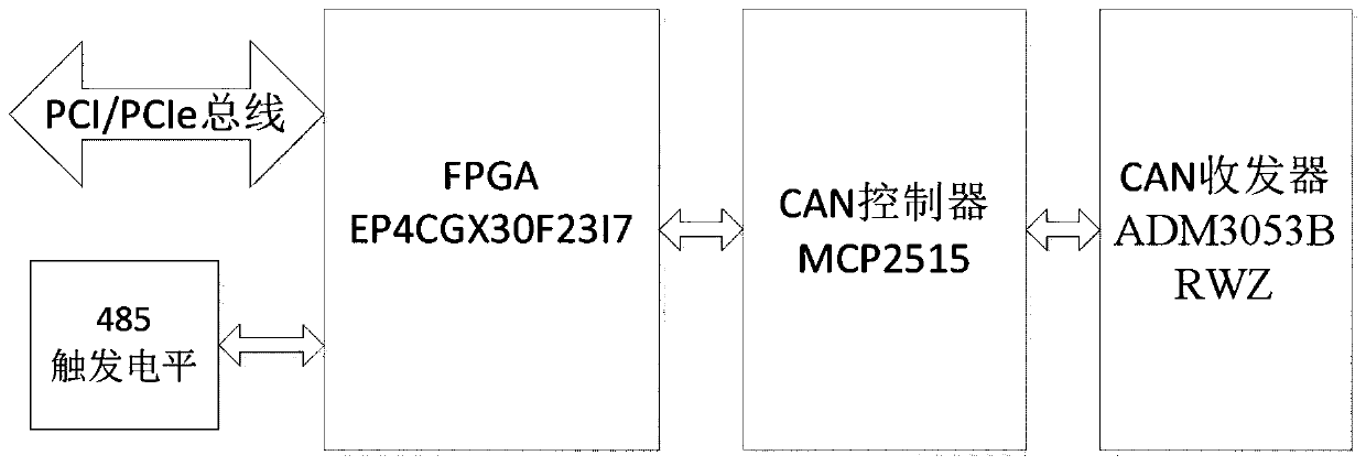
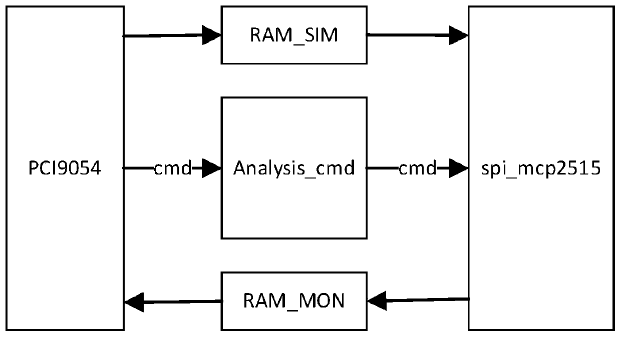
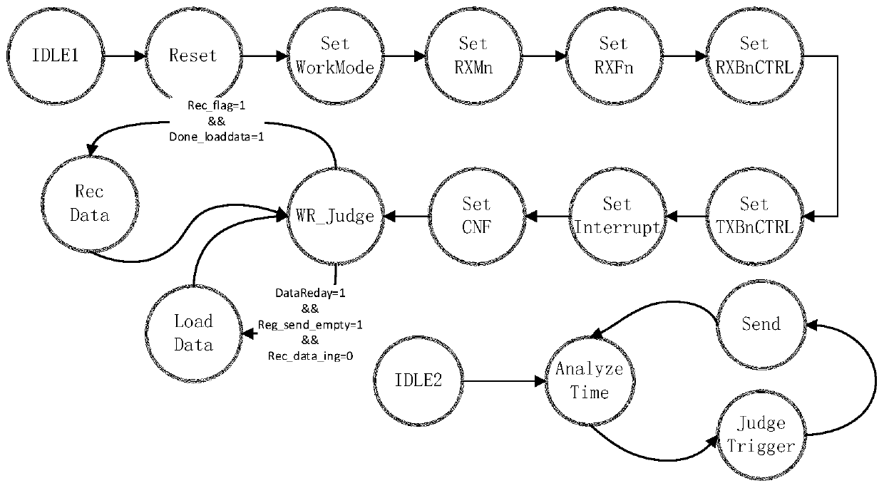
[0100] In order to solve the problems of poor real-time performance of the current CAN communication module or CAN card, insufficient function of trigger control data transmission and reception, lack of timing transmission function, insufficient data shielding reception function, etc., this embodiment provides a set of design schemes for CAN bus data transmission and reception, such as figure 1 The FPGA logic design is shown:

[0101] The innovation points are:

[0102] 1. Use the MCP2515 to have three data buffers. During the initialization process after power-on, write the data to be sent to the three buffers first; during the sending process, monitor the status of the three buffers and find any buffer After the data is read, new data is written to the buffer immediately (while data is written to this buffer, any one of the other two buffers is in the state of sending data). The ability to realize this feature depends on the fact that the MCP2515 has three relatively indepe...


PUM


Abstract

The invention belongs to the technical field of CAN bus communication engineering, and particularly relates to a CAN bus simulation monitoring system. Compared with the prior art, the CAN bus simulation monitoring scheme designed by the invention utilizes the advantages of a hardware scheme and a logic architecture to improve the real-time performance of data transmission; in addition, the functions of triggering and controlling data receiving and sending, setting timing time to complete data sending, shielding and receiving settable data and the like are added. The adaptability of the CAN busin different industry applications is improved, and various use requirements are met.

Description

technical field [0001] The invention belongs to the technical field of CAN bus communication engineering, in particular to a CAN bus simulation monitoring system. Background technique [0002] With the rapid development of information technology, users have higher and higher real-time requirements for CAN bus-based communication. At the same time, there are more requirements for the functions of sending and receiving data at regular intervals and triggering control of sending and receiving data, especially in industries with high reliability and safety requirements. However, most of the current mature CAN communication modules or boards have real-time performance at the ms level, and do not have the functions of sending and receiving data at regular intervals or controlling data sending and receiving through triggering, which limits the performance of some products in the CAN bus communication industry. [0003] The mainstream CAN communication modules or boards on the mark...

Claims


Application Information

Patent Timeline
Patent Type & Authority Applications(China)
IPC IPC(8): G05B23/02
CPCG05B23/0213G05B2219/24065
Inventor 张榕孙笠森孟琪康建涛安鹏伟李世峰刘冬高米陈宏欣闫贯博
Owner 北京京航计算通讯研究所
Learn More