Pull ring unlocking structure of optical module

An optical module, unlocking technology, applied in the field of optical communication, can solve the problem that the optical module is not easy to unlock and so on

Inactive Publication Date: 2020-05-15
INNOLIGHT TECHNOLOGY (SUZHOU) LTD
View PDF6 Cites 1 Cited by
  • Summary
  • Abstract
  • Description
  • Claims
  • Application Information

AI Technical Summary

Problems solved by technology

[0003] The purpose of this application is to provide an optical module pull ring unlocking structure, which solves the problem that the optical module is not easy to unlock from the cage due to poor size, effectively improves the unlocking performance of the optical module, and can meet the requirements of the optical module specified by MSA Size requirements

Method used


Image

  • Pull ring unlocking structure of optical module
  • Pull ring unlocking structure of optical module
  • Pull ring unlocking structure of optical module

Examples


Embodiment 1

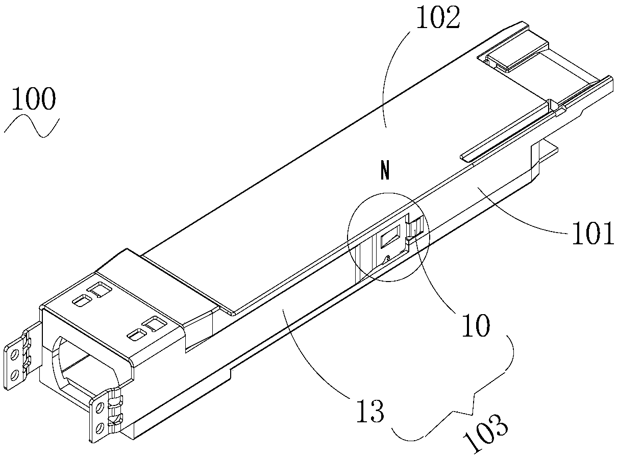
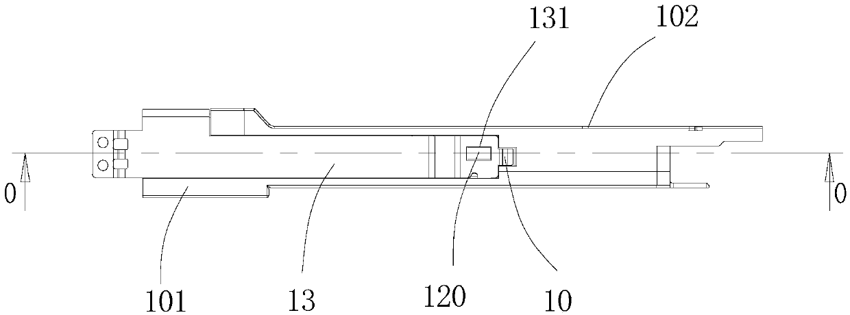
[0030] Please refer to figure 1 , figure 1 It is a three-dimensional view of an optical module. The optical module 100 of this embodiment includes a base 101 , an upper cover 102 and a pull ring 103 . The pull ring 103 is installed on the base 101, and the base 101 and the upper cover 102 are fixed and installed by screws. The pull ring 103 is composed of a tongue 10, a ring arm 13 and a handle (not shown). Both sides of the pull ring 103 are ring arms 13 , and the top end is integrally formed with the ring arm and has a bent tongue 10 , the width of the tongue 10 is smaller than that of the ring arm 13 . The tongue 10 and the ring arm 13 are integrally processed by metal material, and the handle can be made of soft rubber material.

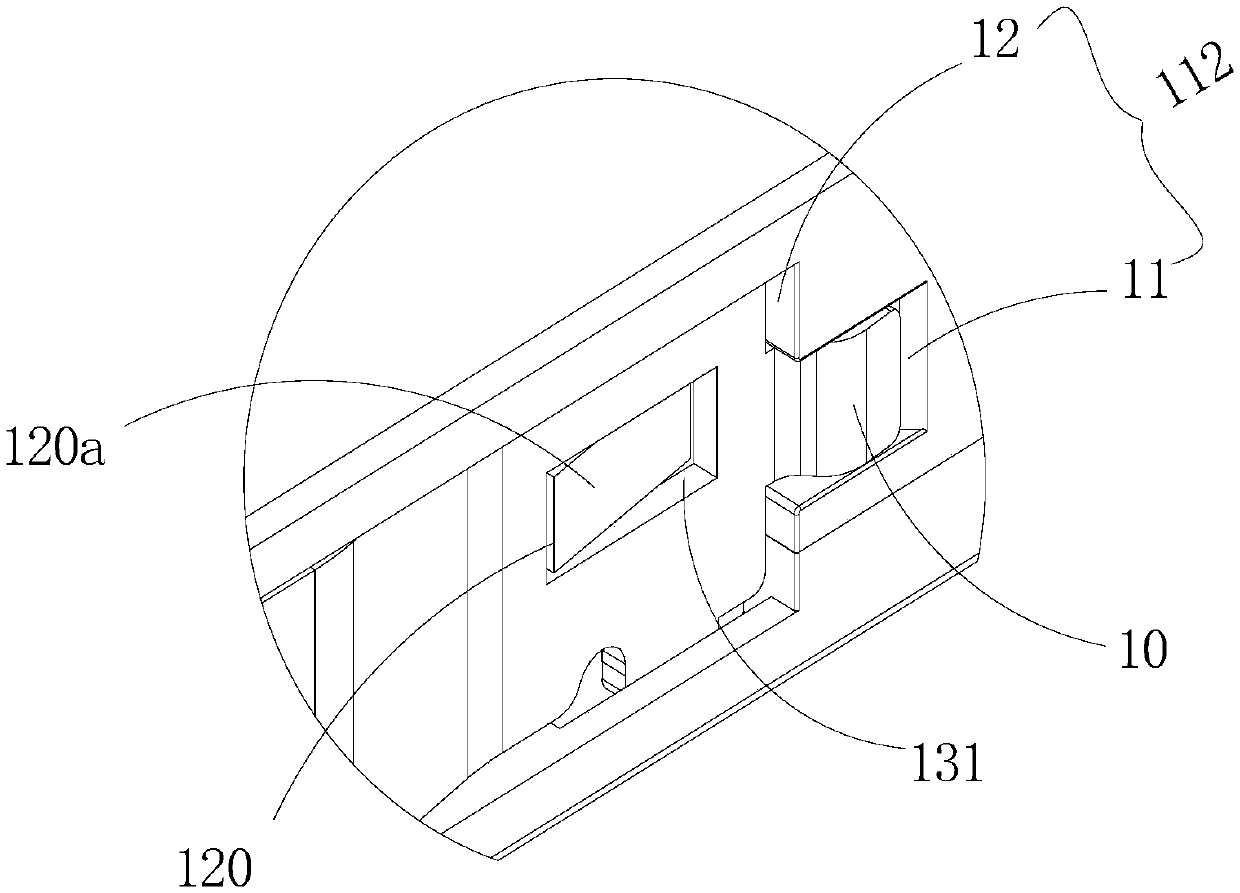
[0031] figure 2 yes figure 1 An enlarged schematic diagram of part N in the optical module shown. Two mounting slots are defined on both sides of the base 101 of the optical module 100 . figure 2 The two installation grooves on one side ...

Embodiment 2

[0035] This application also provides another embodiment, please refer to Figure 6-Figure 8 . The optical module 200 of this embodiment includes a base 201 , an upper cover 202 and a pull ring 203 . The pull ring 203 is installed on the base 201, and the base 201 and the upper cover 202 are fixed and installed by screws. The pull ring 203 is composed of a tongue 20, a ring arm 23 and a handle (not shown). Both sides of the pull ring are ring arms 23 , and the top end is integrally formed with the ring arm 23 and has a bent tongue piece 20 , whose width is smaller than that of the ring arm 23 . The tongue piece 20 and the ring arm 23 are integrally processed by metal material, and the handle can be made of soft rubber material.

[0036]There are two installation grooves on both sides of the base 101 respectively. The width of the first installation groove 21 is smaller than that of the second installation groove 22 . The difference from Embodiment 1 is that an escape groov...


PUM


Abstract

The invention discloses a pull ring unlocking structure of an optical module. The pull ring unlocking structure comprises a base, an upper cover and a pull ring which are assembled together. Mountinggrooves are formed in the two sides of the base, and the pull rings are arranged in the mounting grooves. A protruding block with an inclined face is arranged in the installation groove, and a receding hole matched with the protruding block is formed in the pull ring. During unlocking, the pull ring is pulled, the protruding block expands the tongue piece outwards when the pull ring retreats, thelocking piece of the cage is jacked up, and the optical module is disengaged from the cage. Or the receding groove is formed in the installation groove, the protruding block which is matched with thereceding groove and provided with the inclined face is arranged on the pull ring, and the same unlocking effect can also be achieved. The optical module unlocking device is simple in structure, convenient to manufacture, high in reliability and capable of achieving rapid unlocking of the optical module.

Description

technical field [0001] The present application relates to the field of optical communication, in particular to an unlocking structure of a pull ring of an optical module. Background technique [0002] At present, when a common hot-swappable optical module is inserted into the cage, the locking piece locks and fixes the optical module. When you want to pull out the optical module, you only need to pull the pull ring, back through the pull ring, the tongue will lift the locking pieces on both sides of the cage to realize the unlocking function, so that the optical module is separated from the cage. And the MSA protocol stipulates that the total width of the optical module with the tongue cannot exceed 0.1mm of the original module. Therefore, the optical module must not only achieve the unlocking function, but also meet the size requirements, and the production tolerance requirements for the tongue are relatively strict. If the size is not in place, or the slump angle at the f...

Claims


Application Information

Patent Timeline
IPC IPC(8): G02B6/42
CPCG02B6/4261
Inventor 周贤王克武
Owner INNOLIGHT TECHNOLOGY (SUZHOU) LTD
Why Eureka
Try Eureka