Anti-technical-unlocking lock cylinder device

A technology of a self-locking device and a lock head, applied in the field of pinball locks, can solve the problems that pinball locks are easily unlocked by technology, pinball locks cannot be unlocked by technology, and keys are not unlocked by keys, and it is difficult to unlock by technology. Effect

Inactive Publication Date: 2014-10-22
李国翔
View PDF6 Cites 0 Cited by
  • Summary
  • Abstract
  • Description
  • Claims
  • Application Information

AI Technical Summary

Problems solved by technology

[0004] 1. The end of the pin is exposed and the working stroke is short, the pin can be directly touched by foreign objects (wire hooks, etc.), the pin is easy to fail, the lock cylinder rotates, and it is easy to be opened by technology;
[0005] 2. All keys other than the original lock can enter the lock cylinder, which may easily cause mutual opening with the borrowed key and unequal key teeth;
[0007] The disadvantages of the above-mentioned tumbler lock being easy to be unlocked by technology have seriously affected the safety of users' lives and property. Therefore, a tumbler lock head device that is anti-technically unlocked has been invented, so that the tumbler lock cannot be unlocked by technology, which is exactly the market demand. Urgent needs

Method used


Image

  • Anti-technical-unlocking lock cylinder device
  • Anti-technical-unlocking lock cylinder device
  • Anti-technical-unlocking lock cylinder device

Examples


Embodiment 1

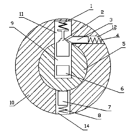
[0035] Such as figure 1 , figure 2 , image 3 As shown, a lock device for anti-technology unlocking includes a lock body 10 and a lock core 5 disposed in the lock body 10, the lock body 10 is provided with a lock body pin 7 and a lock body spring 8, There is a lock pin hole 9 in the lock core 5, and a lock core pin 6 is arranged in the lock core pin hole 9, and a self-locking device is additionally provided in the lock head body 10. The self-locking device includes an anti-lock spring 1, an anti-lock pin 2, a tapered locking pin 3 and a locking spring 4. The anti-lock spring 1 and the anti-lock pin 2 are placed in the anti-lock pin hole 11 in the lock body 10, and the tapered locking pin 3 and the locking spring 4 are placed in the locking pin hole 12 in the lock head body 10, and the anti-locking pin hole 11 communicates with the locking pin hole 12 vertically. The anti-lock pin 2 is a concave anti-lock pin in the middle, and the concave part in the middle is a combinatio...

Embodiment 2

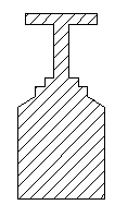
[0038] Such as Figure 4 As shown, the shape and structure of the anti-lock pin 2 can also be a concave zigzag shape in the middle. Other structures are as in the first embodiment. 5 locked.

Embodiment 3

[0040] Such as Figure 5 , Image 6 , Figure 7 , Figure 8 As shown, a lock device for anti-technology unlocking includes a lock body 10 and a lock core 5 disposed in the lock body 10, the lock body 10 is provided with a lock body pin 7 and a lock body spring 8, There is a lock pin hole 9 in the lock core 5, and a lock core pin 6 is arranged in the lock core pin hole 9, and a self-locking device is additionally provided in the lock head body 10. The self-locking device includes a conduit 13 and an anti-lock spring 1 and an anti-lock pin 2 placed in the conduit 13. The conduit 13 is arranged in the lock body 10 and communicates with the pin hole 9 of the lock cylinder. The diameter of the conduit is equal to the diameter 14 of the pin hole of the lock body. There is a sawtooth-shaped concave lower portion at the middle position of the inner wall of the conduit 13 . The anti-lock pin 2 is rounded truncated, the diameter of the lower bottom of the anti-lock pin 2 is smaller ...


PUM


Abstract

The invention discloses an anti-technical-unlocking lock cylinder device comprising a lock cylinder body and a plug arranged inside the lock cylinder body. The lock cylinder body comprises lock cylinder body pins and lock cylinder body springs. The plug is internally provided with plug pin holes; a plug pin is disposed inside each plug pin hole. The anti-technical-unlocking lock cylinder device is characterized in that self-locking devices are added into the lock cylinder body. double-locking pins on the lock cylinder body center the plug pin holes, the plug is locked, the double-locking pins are locked and cannot reversely move, the plug is clamped and locked by the multiple self-locking devices, technical unlocking is more difficult, and a pin tumbler lock is technically unlocked rarely.

Description

technical field [0001] The invention relates to the technical field of pin locks, in particular to an anti-technology unlocking lock head device suitable for pin locks. Background technique [0002] A pin tumbler lock, also known as a marble lock, bead lock, bolt lock or pin lock, is one of the most common locks. Its structural principle is to use a plurality of cylindrical marbles of different heights to lock the lock cylinder. When the correct key is put in, each marble is pushed to the same height, and the lock cylinder can be turned to unlock when the lock cylinder is released. [0003] It has been more than 150 years since the tumbler lock came out, and it is still widely used. It is a relatively common lock on the market. However, due to the widespread use of pin lock technology, the disadvantages of pin locks are becoming more and more obvious, mainly in the following three aspects: [0004] 1. The end of the pin is exposed and the working stroke is short, the pin c...

Claims


Application Information

Patent Timeline
Patent Type & Authority Applications(China)
IPC IPC(8): E05B27/00E05B15/14
Inventor 李国翔
Owner 李国翔
Why Eureka
Try Eureka