
Floating unit plate

A unit board and floating board technology, applied in the field of rail transit, can solve the problems of construction space and transportation and hoisting restrictions, poor driving safety, and high maintenance costs, reducing maintenance times and maintenance difficulties, improving service life, and driving safety. high effect

Pending Publication Date: 2020-05-15
CENT SOUTH UNIV
View PDF0 Cites 1 Cited by
  • Summary
  • Abstract
  • Description
  • Claims
  • Application Information

AI Technical Summary

Problems solved by technology

[0004] The invention provides a floating unit slab to solve the technical problems of existing common prefabricated slabs, which are limited by construction space and transportation and hoisting, poor driving safety, poor vibration damping effect and high maintenance cost

Method used


Image

  • Floating unit plate
  • Floating unit plate
  • Floating unit plate

Examples


Embodiment Construction

[0034] The embodiments of the present invention will be described in detail below with reference to the accompanying drawings, but the present invention can be implemented in various ways defined and covered below.

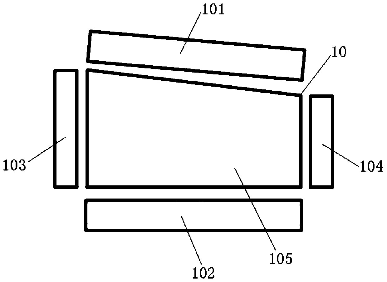
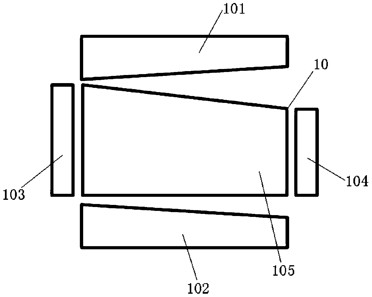
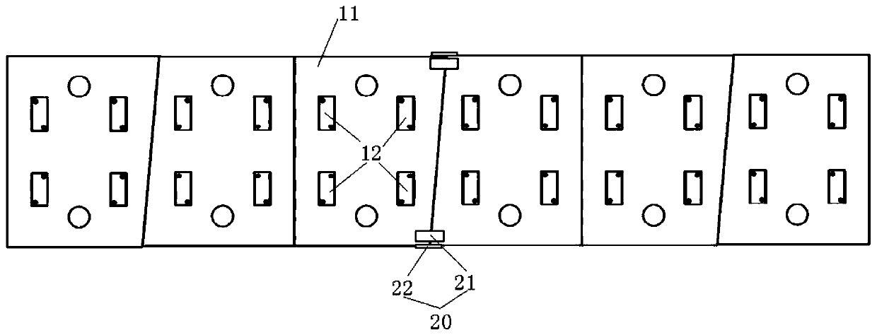
[0035] refer to Figure 1-Figure 12, a preferred embodiment of the present invention provides a floating unit plate, including: a plurality of floating plate unit blocks 10 and a connecting assembly 20, the plurality of floating plate unit blocks 10 are arranged in sequence along the extending direction of the track line and are spliced ​​and connected, The connection assembly 20 is used for connecting multiple floating plate unit blocks 10 to form a floating unit plate. The floating plate unit block 10 is provided with a first splicing surface 101 and a second splicing surface 102 arranged oppositely, the first splicing surface 101 and the second splicing surface 102 are arranged along the width direction of the floating unit plate, and the first splicing surface...


PUM


Abstract

The invention discloses a floating unit plate which comprises a plurality of floating plate unit blocks and a connecting assembly, the floating plate unit blocks are sequentially arranged in the extending direction of a rail line and connected in a spliced mode, and the connecting assembly is used for connecting the floating plate unit blocks to form the floating unit plate. Each floating slab unit block is provided with a first splicing surface and a second splicing surface which are oppositely arranged; the first splicing face and the second splicing face are both arranged in the width direction of the floating unit plate, the first splicing face and the two adjacent side faces are arranged in an oblique crossing mode to form an oblique face, and the second splicing face and the two adjacent side faces are vertically arranged to form a vertical face or the second splicing face and the first splicing face are symmetrically arranged along the center line face of the floating plate unitblock. The first splicing surfaces of the floating plate unit blocks are spliced and connected with the first splicing surfaces of the adjacent floating plate unit blocks to form a linear floating unit plate; and / or the first splicing surfaces of the floating plate unit blocks are spliced and connected with the second splicing surfaces of the adjacent floating plate unit blocks to form the curvedfloating unit plate.

Description

technical field [0001] The invention relates to the field of rail transportation, in particular to a floating unit plate. Background technique [0002] The floating slab track bed is currently the most effective structure for reducing the vibration and noise of rail transit. Compared with other vibration-absorbing rails, it has significant advantages such as good vibration reduction effect, less post-operation and maintenance costs, and long service life. The floating slab track bed generally adopts the construction method of cast-in-place or prefabricated installation. However, due to the complex structure of the cast-in-place floating slab, the quality of on-site pouring construction is not easy to guarantee, and it is prone to poor appearance, exposed steel bars, surface cracks, and large deviations in the accuracy of track geometry And other issues. [0003] Although ordinary prefabricated floating slabs are suitable for mass production in factories and the construction...

Claims


Application Information

Patent Timeline
Patent Type & Authority Applications(China)
IPC IPC(8): E01B1/00E01B19/00
CPCE01B1/002E01B19/003E01B2201/00E01B2204/09
Inventor 朱志辉刘禹兵曾志平陈伟黄宇佳
Owner CENT SOUTH UNIV
Learn More