Eureka AIR delivers breakthrough ideas for toughest innovation challenges, trusted by R&D personnel around the world.

Suction disc clamp capable of realizing integral displacement

A displacement and suction cup technology, applied in the direction of conveyor objects, transportation and packaging, packaging, etc., can solve the problems of poor universality of suction cup fixtures and inability to work normally, and achieve the effect of good universality

Inactive Publication Date: 2020-05-15
佛山市奥楷机械科技有限公司
View PDF6 Cites 0 Cited by
  • Summary
  • Abstract
  • Description
  • Claims
  • Application Information

AI Technical Summary

Problems solved by technology

[0003] Since the position of the suction cup of the general suction cup fixture is fixed, and the interval between the stick materials in the front and rear two stations is also fixed, therefore, it is necessary to ensure the distance between the adjacent rows of suction cups in the suction cup fixture It is compatible with the interval between the stick-shaped materials in the station, so the versatility of the suction cup fixture is poor; and the interval between the stick-shaped materials in the current station is the same as the interval between the stick-shaped materials in the next station different, it will not work

Method used


Image

  • Suction disc clamp capable of realizing integral displacement
  • Suction disc clamp capable of realizing integral displacement
  • Suction disc clamp capable of realizing integral displacement

Examples


Embodiment Construction

[0027] Embodiments of the present invention are described in detail below, examples of which are shown in the drawings, wherein the same or similar reference numerals denote the same or similar elements or elements having the same or similar functions throughout. The embodiments described below by referring to the figures are exemplary only for explaining the present invention and should not be construed as limiting the present invention.

[0028] In describing the present invention, it should be understood that the terms "center", "longitudinal", "transverse", "length", "width", "thickness", "upper", "lower", "front", " Orientation indicated by rear, left, right, vertical, horizontal, top, bottom, inside, outside, clockwise, counterclockwise, etc. The positional relationship is based on the orientation or positional relationship shown in the drawings, which is only for the convenience of describing the present invention and simplifying the description, rather than indicating ...


PUM


Abstract

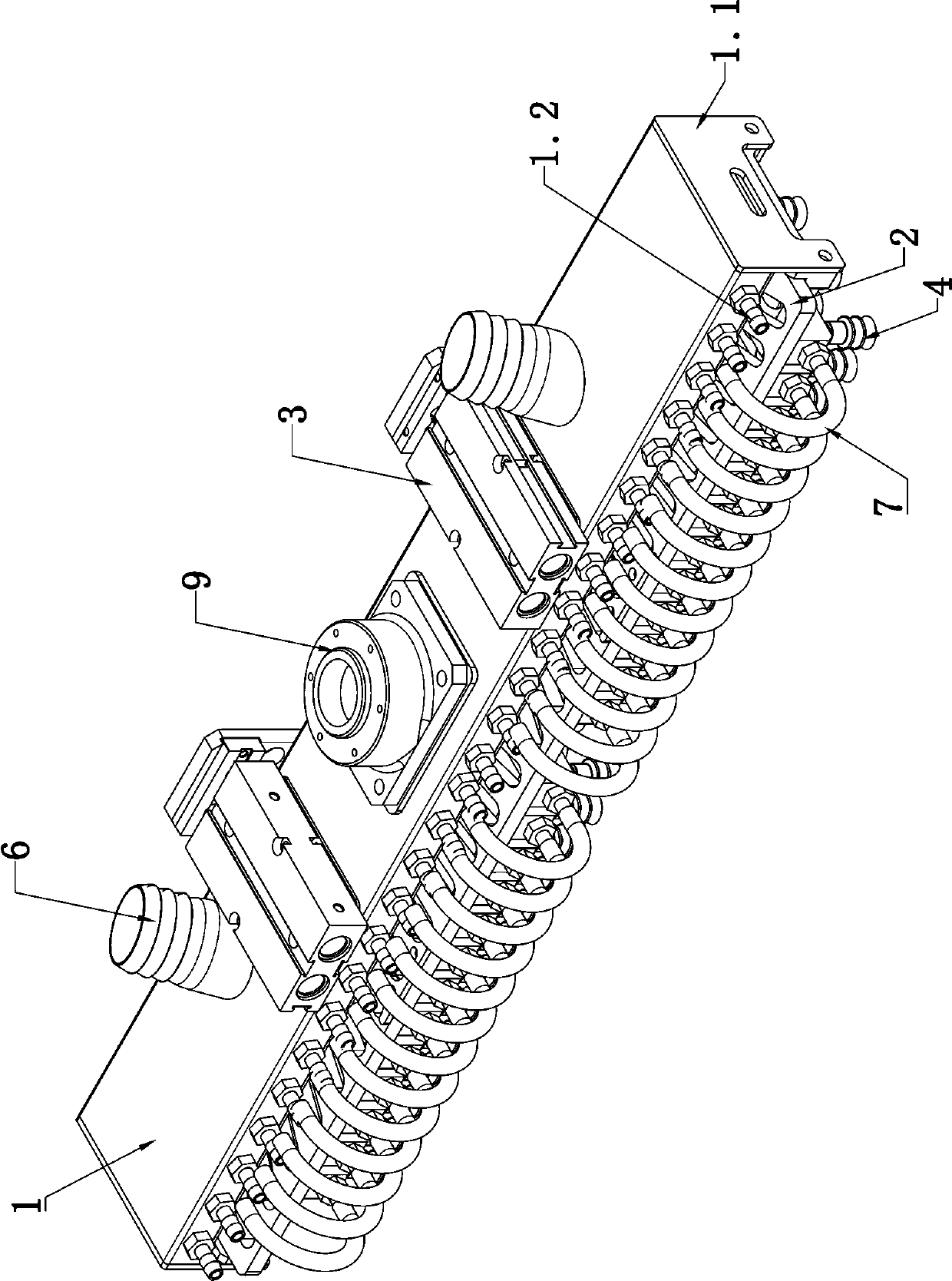
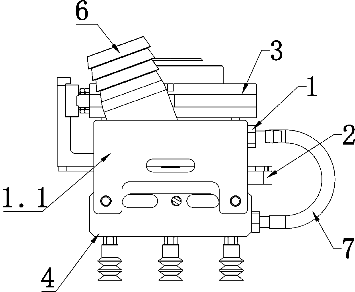
The invention provides a suction disc clamp capable of realizing integral displacement. The suction disc clamp capable of realizing integral displacement comprises a top plate used for being connectedwith a mechanical arm, a displacement plate arranged below the top plate in parallel and capable of moving forwards and backwards, a drive device used for driving the displacement plate to move forwards and backwards, and a plurality of suction disc assemblies arranged below the displacement plate in a manner of moving to the left and the right, wherein at least one group of slide grooves is formed in the displacement plate, and each group comprises a plurality of slide grooves arranged in the left-right direction; in the same group of slide grooves, the distance between any two adjacent slide grooves is gradually increased / reduced from the front to the rear, and the interval between the slide grooves is equal on any same front-rear position; each suction disc assembly comprises a slide block capable of moving to the left and the right, a slide pin arranged at the top of the slide block, and at least two suction discs arranged at the bottom of the slide block in the front-rear direction; and the slide pins are inserted into the different slide grooves separately. The distances among the columns of suction discs in the suction disc clamp can be adjusted on line.

Description

technical field [0001] The invention relates to the technical field of packaging machinery and equipment, in particular to an integrally displaceable suction cup clamp. Background technique [0002] At present, in the process of packaging some stick-shaped materials (such as sausages), it is necessary to use a mechanical arm to transfer the material from one station to another. Usually, the stick-shaped materials are arranged in a full-page layout, so they will be placed in the A suction cup fixture is set on the mechanical arm to transfer the material in a full-page manner. There are multiple suction cups arranged in a dot matrix at the bottom of the suction cup fixture. Each stick-shaped material is usually absorbed by at least two suction cups. [0003] Since the position of the suction cup of the general suction cup fixture is fixed, and the interval between the stick materials in the front and rear two stations is also fixed, therefore, it is necessary to ensure the dis...

Claims


Application Information

Patent Timeline
Patent Type & Authority Applications(China)
IPC IPC(8): B65B35/38B65G47/91
CPCB65B35/38B65G47/91B65G2207/08
Inventor 熊洪杜功德邱亿辉
Owner 佛山市奥楷机械科技有限公司
Why Eureka
Eureka Blog
Learn More