
Vehicle front windscreen wiper mounting structure and front windscreen wiper system

A technology of installation structure and front rain, which is applied in vehicle maintenance, vehicle parts, vehicle cleaning, etc., can solve the problem of not meeting the requirements of consumers' sound quality, affecting the sound quality of wiper wipers, and the inching stiffness of wiper installation No high problems, to achieve the effect of reducing weight, reducing the size of parts, and reducing the probability of shaking

Inactive Publication Date: 2020-05-15
LAUNCH DESIGN INC LTD
View PDF11 Cites 0 Cited by
  • Summary
  • Abstract
  • Description
  • Claims
  • Application Information

AI Technical Summary

Problems solved by technology

[0005] The dynamic stiffness of the wiper installation point in the above-mentioned automobile front wiper system is not high, and the wiper is directly connected to the lower beam of the windshield by bolts. The bolted connection between the gutters will become loose or worn. At this time, when the car is using the wiper, the noise will also increase, which will affect the sound quality of the wiper when it is wiped, and it will not meet the sound quality that consumers expect from the car. Therefore, the installation structure of the existing automobile front wiper system needs to be optimized

Method used


Image

  • Vehicle front windscreen wiper mounting structure and front windscreen wiper system
  • Vehicle front windscreen wiper mounting structure and front windscreen wiper system
  • Vehicle front windscreen wiper mounting structure and front windscreen wiper system

Examples


Embodiment Construction

[0038] The present invention will be described in further detail below in conjunction with the accompanying drawings.

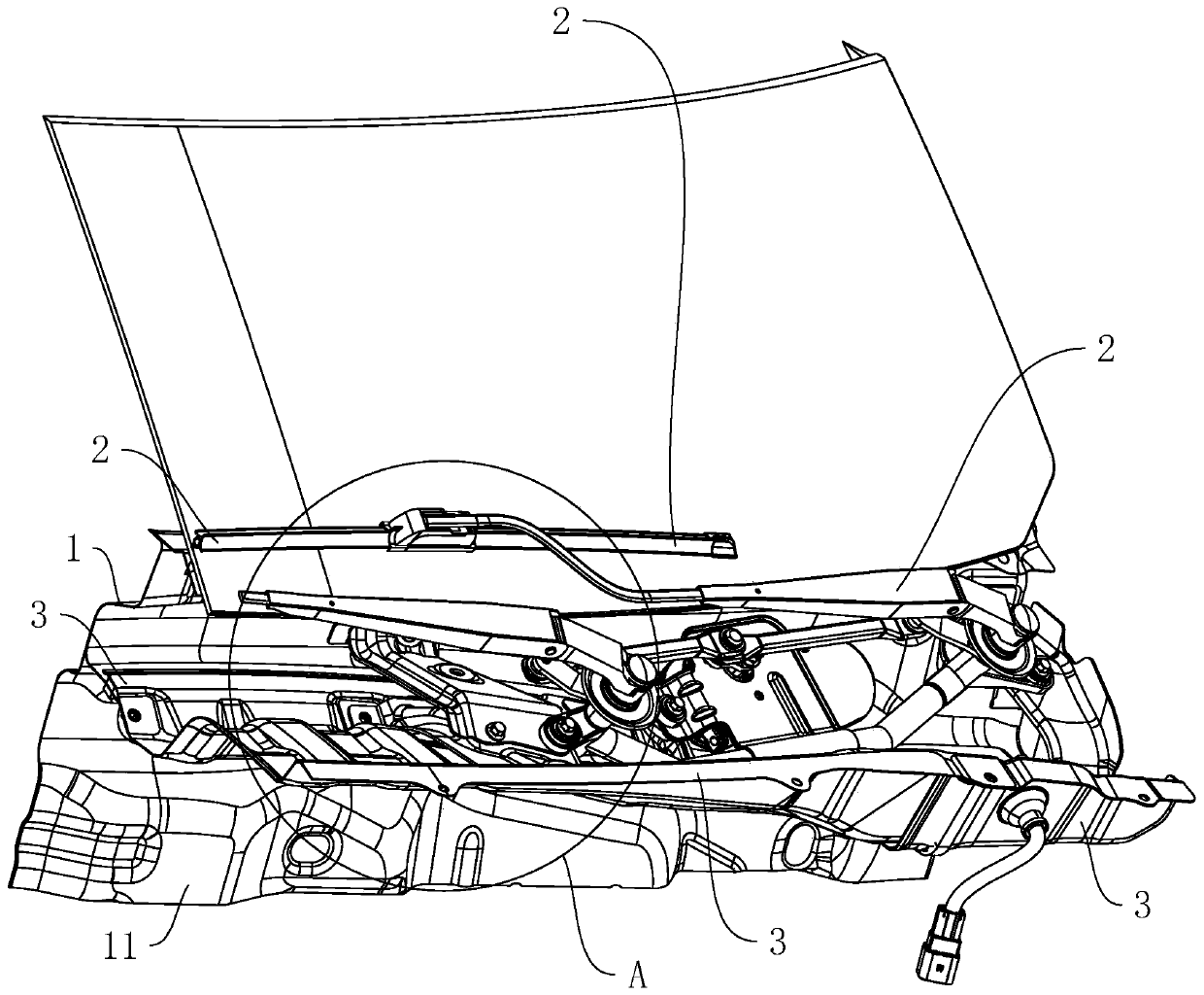
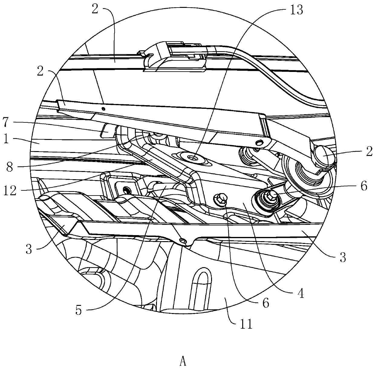
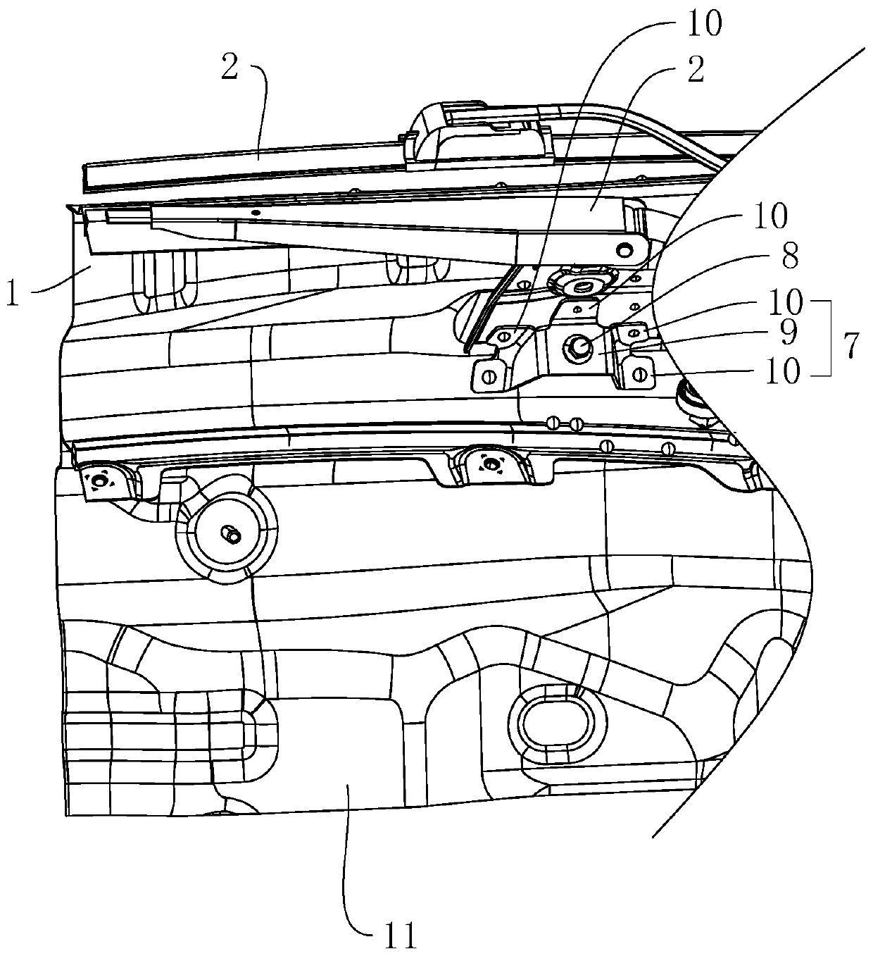
[0039] A vehicle front wiper installation structure, which is located at the lower beam 1 of the windshield of the car, and can be used to stably install the wiper 2 at the front windshield of the car, such as figure 1 and figure 2 As shown, the wiper 2 is provided with a wiper installation connecting bracket 4 at one end close to the lower beam 1 of the windshield, wherein the wiper installation connecting bracket 4 is in the shape of a "Z" (see figure 1 ), the wiper installation connection bracket 4 is provided with a support plate 7 in the middle of the windshield lower beam at the end away from the wiper 2 (see image 3). At the same time, there is a flange 12 on the edge of the wiper installation connecting bracket 4, the existence of the above flange 12 effectively improves the tightness of the direct bonding between the wiper installation connecting...


PUM


Abstract

The invention discloses a vehicle front windscreen wiper mounting structure and a front windscreen wiper system. The invention belongs to the technical field of automobile parts. The front windshieldwiper mounting structure a front windscreen wiper middle nut plate, a windscreen lower cross beam middle supporting plate, and a windscreen wiper installation connecting support for connecting the front windscreen wiper middle nut plate and the windscreen lower cross beam middle supporting plate, wherein the windscreen wiper installation connecting support is fixedly connected to the end, close tothe front windscreen wiper middle nut plate, of the windscreen wiper; the front windscreen wiper middle nut plate is fixedly connected into a front gutter channel; the front windscreen wiper middle nut plate is in a closed box shape; and the windscreen lower beam middle supporting plate is fixedly connected to a windscreen lower beam. The vehicle front windscreen wiper system comprises a windscreen lower cross beam and a windscreen wiper rotationally connected to the windscreen lower cross beam, wherein a front gutter channel is formed in the windscreen lower cross beam. The front windscreenwiper system further comprises the vehicle front windscreen wiper mounting structure. The windscreen wiper installation connecting support not only has an effect of a windscreen wiper, but also can improve the dynamic rigidity of windscreen wiper installation points, the effect of improving the mode of the front gutter channel can be achieved, and vibration of the front gutter channel body is reduced.

Description

technical field [0001] The invention belongs to the technical field of auto parts, and more specifically relates to a vehicle front wiper installation structure and a front wiper system. Background technique [0002] At present, the competition in the automobile industry is becoming more and more fierce, and the manufacturing cost control is becoming more and more refined. The installation structure of the existing automobile front wiper system mainly includes fan pressure chamber plate, wiper motor bracket, wiper connecting rod left bracket, wiper connecting rod middle bracket and other parts, and its main purpose is to install the wiper The axis of rotation of the motor and wiper linkage. Among them, the wiper is an important part of the car. The wiper generally has a long cantilever structure. If the dynamic stiffness of the wiper installation point is insufficient, the wiper is prone to noise and vibration during work. [0003] The main function of the front gutter on ...

Claims


Application Information

Patent Timeline
Patent Type & Authority Applications(China)
IPC IPC(8): B60S1/04B60R13/07
CPCB60R13/07B60S1/043B60S1/0441
Inventor 蒋光阳曾厚旭马强强张祖蔚张强胡亚飞
Owner LAUNCH DESIGN INC LTD
Learn More