
Power unit

A technology for power units and power components, which is used in output power conversion devices, electrical components, cooling/ventilation/heating renovations, etc. It can solve the problems of inconvenient removal, maintenance and replacement of cooling fans, and ensure path consistency and structure. Compact, heat-reducing effect

Pending Publication Date: 2020-05-12
CSR ZHUZHOU ELECTRIC LOCOMOTIVE RES INST
View PDF4 Cites 0 Cited by
  • Summary
  • Abstract
  • Description
  • Claims
  • Application Information

AI Technical Summary

Problems solved by technology

[0006] In view of this, the purpose of the present invention is to provide a power unit to solve the technical problem of inconvenient removal, maintenance and replacement of the cooling fan of the existing power module

Method used


Image

  • Power unit
  • Power unit
  • Power unit

Examples


Embodiment Construction

[0035] In order to make the purpose, technical solutions and advantages of the embodiments of the present invention more clear, the technical solutions in the embodiments of the present invention will be clearly and completely described below in conjunction with the drawings in the embodiments of the present invention. Apparently, the described embodiments are only some of the embodiments of the present invention, not all of them. Based on the embodiments of the present invention, all other embodiments obtained by persons of ordinary skill in the art without creative efforts fall within the protection scope of the present invention.

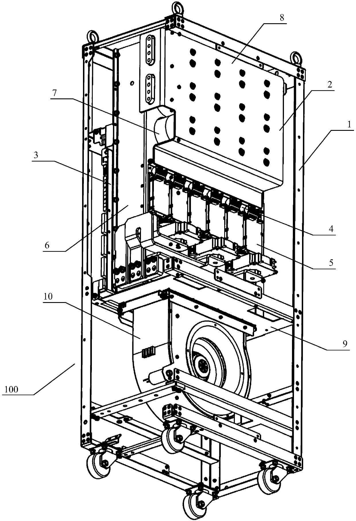
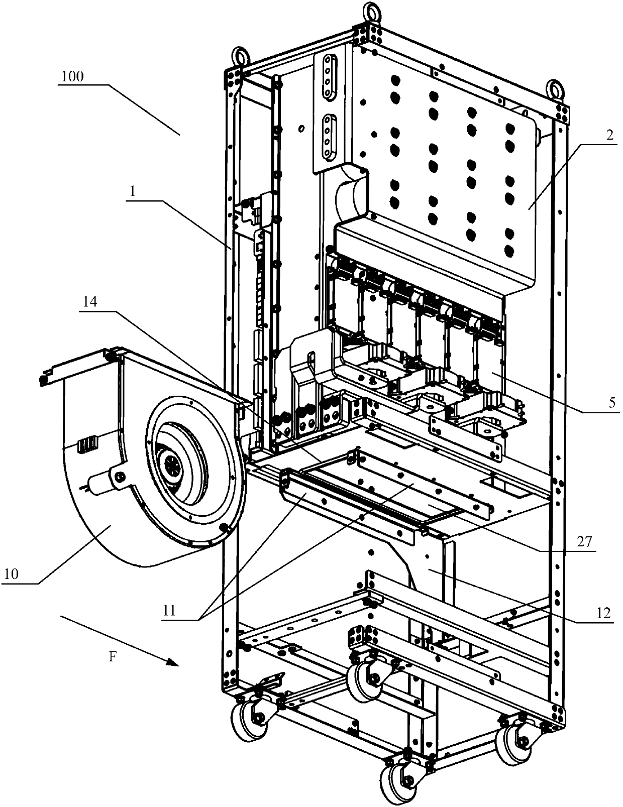
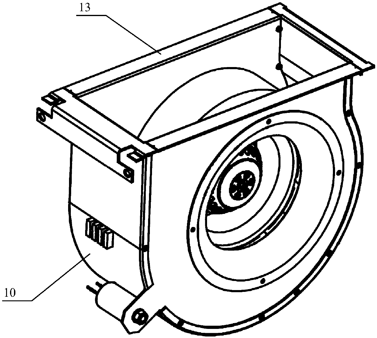
[0036] as attached figure 1 to attach Figure 11 As shown, specific embodiments of the power unit of the present invention are given, and the present invention will be further described below in conjunction with the drawings and specific embodiments.

[0037] as attached figure 1 to attach image 3 As shown, an embodiment of a power unit is a...


PUM


Abstract

The invention discloses a power unit, wherein a bearing plate is fixed on a framework of a cabinet body, a power module is arranged on the bearing plate, and comprises a box body with upper and loweropenings, the bottom of the box body is tightly attached and fixed to the upper portion of the bearing plate to form a first air duct, lower push-in guide rails and upper push-in guide rails are oppositely arranged in parallel in the vertical direction and are arranged at the bottom of the bearing plate in parallel in pairs and opposite to each other, an air duct opening is formed in the bearing plate and located between the two pairs of the lower push-in guide rails and the two pairs of the upper push-in guide rails, a fan is pushed in and fixed between the lower push-in guide rail and the upper push-in guide rail through a fan guide rail arranged at the top of the fan, the power module further comprises a power element and a radiator arranged in the box body, the power element is installed on the radiator, and the radiator is buried in the first air duct defined by the box body. According to the invention, the technical problem that the existing power module cooling fan is inconvenient to disassemble, maintain and replace can be solved.

Description

technical field [0001] The present invention relates to the technical field of electrical equipment, in particular to a fast push-in fan power unit structure with an air-cooled power module. Background technique [0002] At present, wind energy and solar energy are renewable energy sources that are widely used in my country. The power modules in wind power converters and photovoltaic inverters change the characteristics of the input voltage by controlling the power elements to be turned on and off, and play the role of rectification and inversion. Power modules are increasingly widely used in converters due to their light weight, convenient disassembly, and easy maintenance. Among them, the power module with IGBT (Insulated Gate Bipolar Transistor, short for Insulated Gate Bipolar Transistor) as the core component usually integrates radiators, DC support capacitors, composite busbars, related drive and control modules and other devices. IGBT devices are used as power compo...

Claims


Application Information

Patent Timeline
Patent Type & Authority Applications(China)
IPC IPC(8): H02M1/00H05K7/20H05K5/02H05K7/14
CPCH02M1/00H05K7/20909H05K5/0213
Inventor 黄南邵强蒋云富王世平胡长风石廷昌翟龙
Owner CSR ZHUZHOU ELECTRIC LOCOMOTIVE RES INST
Learn More