Power conversion device and heat dissipation system thereof

A technology of power conversion device and heat dissipation system, which is applied in the field of rail transit, and can solve problems such as large module power loss, heat accumulation, power module of power conversion device, and high failure rate of electronic components

Inactive Publication Date: 2020-05-12
ZHUZHOU CSR TIMES ELECTRIC CO LTD
View PDF5 Cites 2 Cited by
  • Summary
  • Abstract
  • Description
  • Claims
  • Application Information

AI Technical Summary

Problems solved by technology

[0002] For high-power power conversion devices used in rail transit, due to their high operating power, the power loss of their internal modules is large. The cooling system of power conversion devices in this field generally uses forced water circulation to dissipate heat. The heat generated by the power loss of the modules and other heat-generating components is conducted to the coolant through the water-cooled plate, and then dissipated to the outside through the water circulation through liquid-gas heat exchange, but the high-power modules and other heat-generating components are naturally radiated to the air in the electrical cabin Because the air in the electrical cabin is closed and the air does not circulate, it is easy to cause heat accumulation and cause local hot spots in the power conversion device, and the heat in the electrical cabin can only be radiated and exchanged slowly through the cabinet body, resulting in power modules, electronic components, etc. inside the power conversion device. high failure rate

Method used


Image

  • Power conversion device and heat dissipation system thereof
  • Power conversion device and heat dissipation system thereof
  • Power conversion device and heat dissipation system thereof

Examples


Embodiment Construction

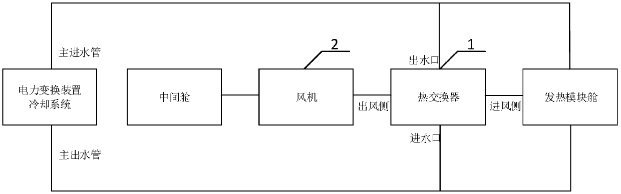
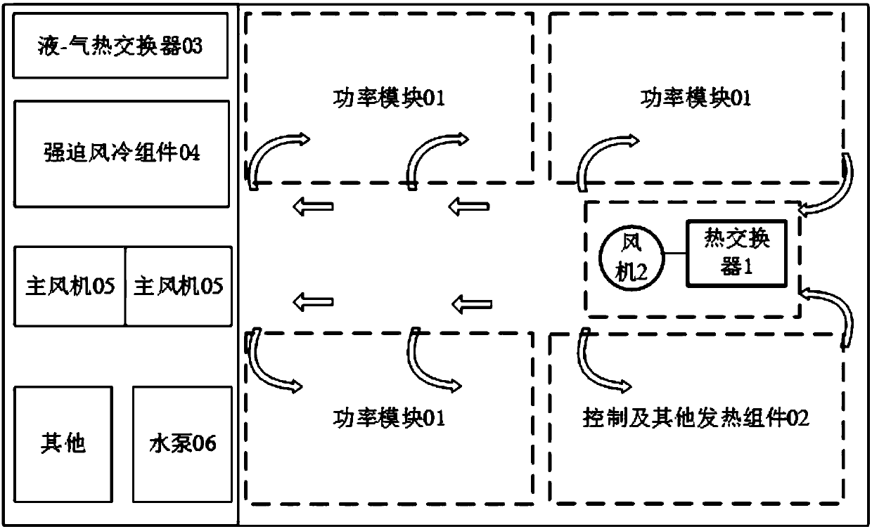
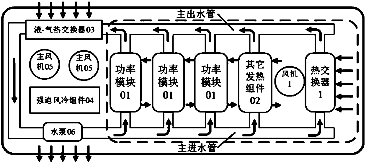
[0033] The core of the present invention is to provide a heat dissipation system for a power conversion device. The fan stirs the air in the electrical cabin to make it flow, avoiding the occurrence of local hot spots in the electrical cabin, and at the same time realizes the external heat exchange of the heat in the electrical cabin through a heat exchanger. , which greatly improves the operating temperature in the electrical compartment of the power conversion device, and improves the life and reliability of the electrical components inside the power conversion device; another core of the present invention is to provide a power conversion device including the above-mentioned heat dissipation system.

[0034] In order to make the purpose, technical solutions and advantages of the embodiments of the present invention clearer, the technical solutions in the embodiments of the present invention will be clearly and completely described below in conjunction with the drawings in the ...


PUM


Abstract

The invention discloses a heat dissipation system of a power conversion device. The system comprises: a heat exchanger arranged in an electrical cabin, wherein the water inlet of the heat exchanger iscommunicated with the main water inlet pipe of a power conversion device cooling system, the water outlet of the heat exchanger is communicated with the main water outlet pipe of the power conversiondevice cooling system, the wind inlet side of the heat exchanger is communicated with a heating module cabin in the electrical cabin, and the wind outlet side of the heat exchanger is communicated with a middle cabin in the electrical cabin; and a fan for driving air in the electrical cabin to flow so as to cool the air through the heat exchanger. According to the invention, air in an electricalcabin is stirred by a fan to flow so as to avoid the local hot spots in the electrical cabin, and external heat exchange of the heat in the electrical cabin is achieved through a heat exchanger so asto substantially improve the operating temperature in the electrical cabin of the power conversion device and improve the service life and the reliability of the electrical components in the power conversion device. The invention further discloses a power conversion device, which has the above beneficial effects.

Description

technical field [0001] The invention relates to the field of rail transportation, in particular to a power conversion device and a cooling system thereof. Background technique [0002] For high-power power conversion devices used in rail transit, due to their high operating power, the power loss of their internal modules is large. The cooling system of power conversion devices in this field generally uses forced water circulation to dissipate heat. Specifically, the high-power The heat generated by the power loss of the modules and other heat-generating components is conducted to the coolant through the water-cooled plate, and then dissipated to the outside through the water circulation through liquid-gas heat exchange, but the high-power modules and other heat-generating components are naturally radiated to the air in the electrical cabin Because the air in the electrical compartment is closed and the air does not circulate, it is easy to cause heat accumulation and cause l...

Claims


Application Information

Patent Timeline
IPC IPC(8): H02M1/00H05K7/20
CPCH02M1/00H05K7/20909H05K7/20936
Inventor 章志兵祁善军邹档兵徐绍龙唐雄辉刘永江翁星方李华黄浩孙亚运吴刚李文亮罗荣争
Owner ZHUZHOU CSR TIMES ELECTRIC CO LTD
Why Eureka
Try Eureka