Combination electric appliance with port connector

A technology for combined electrical appliances and connectors, which is applied in substation/distribution device shells, busbars/line layouts, etc., can solve problems such as interference, achieve the effects of reducing modifications, ensuring normal installation, and facilitating conductive connections

Active Publication Date: 2021-04-09
HENAN PINGGAO GENERAL ELECTRIC CO LTD +2
View PDF2 Cites 0 Cited by
  • Summary
  • Abstract
  • Description
  • Claims
  • Application Information

AI Technical Summary

Problems solved by technology

[0006] The purpose of the present invention is to provide a combined electrical appliance with a port connector to solve the problem of three-position switch on the incoming line side when adding a three-position switch on the incoming line side of the circuit breaker of the combined electric appliance with a port connector in the prior art. The technical problem of interference between the operating mechanism of the position switch and the barrel of the port connector

Method used


Image

  • Combination electric appliance with port connector
  • Combination electric appliance with port connector
  • Combination electric appliance with port connector

Examples


Embodiment 1

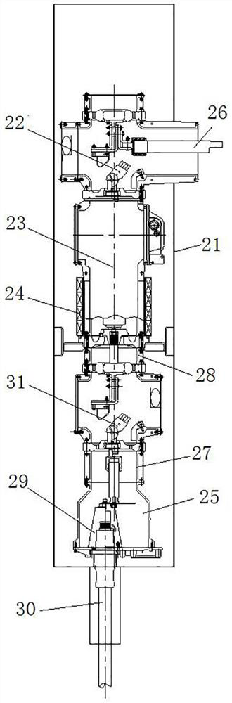
[0033] Such as figure 2 As shown, it includes a cabinet body 21, inside the cabinet body 21 there are three-position switch 22 on the outlet side, a circuit breaker 23, a three-position switch 31 on the incoming line side, a connecting cylinder 27, and a port connector 25. The three-position switch on the outlet side is electrically connected to the outlet busbar 26 , and the bottom of the port connector 25 is fixed with an inner cone insulator 29 , and the conductive insert inside the inner cone insulator 29 is electrically connected to the incoming cable 30 .

[0034] In this embodiment, the three-position switch 22 on the outgoing line side, the circuit breaker 23, and the three-position switch 31 on the incoming line side in the cabinet body 21 are respectively provided with an upper switch operating mechanism and a circuit breaker operating mechanism on one side in the horizontal direction. , Lower switch operating mechanism. Driven by each operating mechanism, when the...

Embodiment 2

[0046] The difference from Embodiment 1 is that no three-position switch on the outgoing line side is installed on the upper part of the circuit breaker, and the outgoing line busbar is directly drawn from the outgoing line side insulator of the circuit breaker.

Embodiment 3

[0048] The difference from Embodiment 1 is that the current transformer can be arranged on the incoming cable, and the specific arrangement can be the arrangement of the current transformer and the cable disclosed in the authorized publication number CN202633809U.


PUM


Abstract

The invention relates to a combined electrical appliance with a port connector. The combined electrical appliance with a port connector includes a circuit breaker and a three-position switch on the incoming line side. The three-position switch on the incoming line side is arranged on the incoming line side of the circuit breaker; It also includes the cabinet body and port connector; the circuit breaker and the three-position switch on the incoming line side are all set in the cabinet; the port connector is set on the side of the three-position switch on the incoming line side away from the circuit breaker; the three-position switch on the incoming line side There is a connecting cylinder between the switch and the port connector, and the connecting cylinder is connected to the three-position switch on the incoming line side and the port connector; the three-position switch on the incoming line side is provided with a switch operating mechanism on one side in the horizontal direction. The switch operating mechanism is used to drive the three-position switch on the incoming line side to open, close and ground; at least a part of the switch operating mechanism in the vertical direction is located radially outside the connecting cylinder; the diameter of the connecting cylinder is smaller than that of the port connection The diameter of the barrel of the device is to avoid the part of the switch operating mechanism on the radially outer side of the connecting barrel.

Description

technical field [0001] The invention relates to a combined electric appliance with a port connector. Background technique [0002] In the prior art, there is generally a three-position switch between the circuit breaker and the busbar of the combined electrical appliance. When the combined electrical appliance is grounded, it needs to go through three steps: opening the circuit breaker, grounding the three-position switch on the outlet side, and closing the circuit breaker. in order to achieve. [0003] In order to meet user program requirements, in the prior art, a three-position switch on the incoming line side is generally added between the circuit breaker and the port connector. For example, the Chinese utility model patent with the authorized announcement number CN203071413U discloses a new type of double-sided isolated grounding combined electrical appliance, including a bottom frame, a circuit breaker is fixed on the bottom frame, and the upper horizontal output end ...

Claims


Application Information

Patent Timeline
Patent Type & Authority Patents(China)
IPC IPC(8): H02B1/20H02B1/30
CPCH02B1/20H02B1/30
Inventor 张海卓会丹王焕刘晓焱刘宁张梦柯侯宾宾王强马琰孙琪郭佩淇
Owner HENAN PINGGAO GENERAL ELECTRIC CO LTD
Why Eureka
Try Eureka