
Storage device of parking charging equipment

A parking charging and storage device technology, applied to ticketing equipment, instruments, etc., can solve the problems of insensitive detection of charging, equipment failure, waste of human resources, etc., and achieve the effect of improving equipment use efficiency and reducing loss

Inactive Publication Date: 2020-05-12
温州市唐豪网络科技有限公司
View PDF0 Cites 8 Cited by
  • Summary
  • Abstract
  • Description
  • Claims
  • Application Information

AI Technical Summary

Problems solved by technology

[0002] At present, parking charging equipment is involved in various residential areas, commercial streets or enterprises, etc. It is mostly used outdoors, and can effectively avoid the disorderly parking of cars and affect the order. The entrances and exits of major parking lots are temporarily equipped with sentry boxes and parking charging equipment. , while the base of the parking charging equipment is fastened with carbon steel and ground screws, which is not easy to move. For some temporary sentry boxes, the only choice is to disassemble and move, which not only wastes human resources, but also the parking charging equipment in the outer room is easily affected by the weather. The impact will lead to the insensitivity of detection and charging, and staying outdoors for a long time will easily lead to equipment failure. At the same time, frequent equipment maintenance also wastes the time of relevant personnel and the efficiency of equipment.

Method used


Image

  • Storage device of parking charging equipment
  • Storage device of parking charging equipment
  • Storage device of parking charging equipment

Examples


Embodiment Construction

[0020] All the features disclosed in this specification, or all disclosed methods or steps in the process, except for mutually exclusive features or steps, can be combined in any manner.

[0021] Combine below Figure 1-6 The present invention will be described in detail. For the convenience of description, the orientations mentioned below are now specified as follows: figure 1 The vertical, horizontal, front and rear directions of the projection relationship are the same.

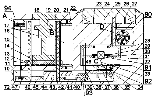
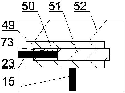
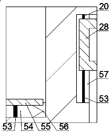
[0022] Such as Figure 1-6 As shown, a storage device for parking toll collection equipment of the present invention includes a housing 10 in which a delay chamber 70 is provided, and the delay chamber 70 is provided with a delay to accommodate parking toll collection equipment The delay mechanism 90 of the delay chamber 70 is provided with a driving chamber 31 in the lower end wall of the delay chamber 70 with an upper opening communicating with the delay chamber 70, and the driving chamber 31 is provided wit...


PUM


Abstract

The invention discloses a storage device of parking charging equipment. The device comprises a shell; a time delay cavity is formed in the shell; a time delay mechanism is arranged in the time delay cavity; a driving cavity is formed in the lower end wall of the time delay cavity; a driving mechanism is arranged in the driving cavity; a switching mechanism is arranged in the lower end wall of thedriving cavity; a transmission cavity is formed in the left side of the switching mechanism; a transmission mechanism is arranged in the transmission cavity; a working cavity is formed in the upper end wall of the transmission cavity; a charging device and a control mechanism are arranged in the working cavity; when an vehicle runs and enters a parking place, by gravity of the vehicle, the drivingmechanism raises the parking charging device to the ground, parking charging timing is provided, and when the vehicle drives away, the time delay mechanism triggers starting, if no vehicle drives toenter for a time, the driving mechanism can store the parking charging device underground, so that the parking charging device stops working, the loss of the parking charging device and the maintenance frequency of the parking charging device caused by external factors such as weather are effectively reduced, and the use efficiency of the parking charging device is improved.

Description

Technical field [0001] The invention relates to the field of parking toll equipment, in particular to a storage device for parking toll equipment. Background technique [0002] At present, parking charging equipment is involved in various communities, commercial streets or enterprises. It is mostly used outdoors, and it can effectively prevent the disordered parking of cars from affecting the order. The entrances and exits of major parking lots are temporarily equipped with guard booths and parking charging equipment. However, the base of the parking toll device is fastened with carbon steel and ground screws, which is not easy to move. For some temporary guard posts, the only choice is to disassemble and move, which not only wastes human resources, but also the parking toll device in the outer room is vulnerable to weather This will cause problems such as insensitive detection and charging, and staying outdoors for a long time will easily lead to equipment failure. At the same t...

Claims


Application Information

Patent Timeline
IPC IPC(8): G07B15/06
CPCG07B15/06
Inventor 不公告发明人
Owner 温州市唐豪网络科技有限公司
Learn More