
Camera displacement changing device for bridge crane

A technology for changing devices and cameras, applied in the direction of supporting machines, mechanical equipment, machines/stands, etc., can solve problems such as difficulty in meeting the viewing angle

Active Publication Date: 2021-08-03
TAIYUAN HEAVY IND
View PDF5 Cites 0 Cited by
  • Summary
  • Abstract
  • Description
  • Claims
  • Application Information

AI Technical Summary

Problems solved by technology

However, bridge cranes are generally located in the upper part of the workshop, and the heavy objects to be lifted are below its running path. In order to monitor the heavy objects to be lifted, it also meets the image requirements of some special cranes, such as casting cranes for molten iron The decoupling recognition of bales, the decoupling recognition of steel coils by clamp cranes, etc., are traditionally used to install cameras on cranes, which are often difficult to meet the viewing angle, especially the viewing angle requirements of image recognition technology.

Method used


Image

  • Camera displacement changing device for bridge crane
  • Camera displacement changing device for bridge crane
  • Camera displacement changing device for bridge crane

Examples


Embodiment Construction

[0034] In order to make the purpose, technical solution and advantages of the present invention clearer, the technical solution of the present invention will be clearly and completely described below in conjunction with specific embodiments of the present invention and corresponding drawings. Apparently, the described embodiments are only some of the embodiments of the present invention, but not all of them. Based on the embodiments of the present invention, all other embodiments obtained by persons of ordinary skill in the art without making creative efforts fall within the protection scope of the present invention.

[0035] The technical solution provided according to an embodiment of the present invention will be described in detail below with reference to the accompanying drawings.

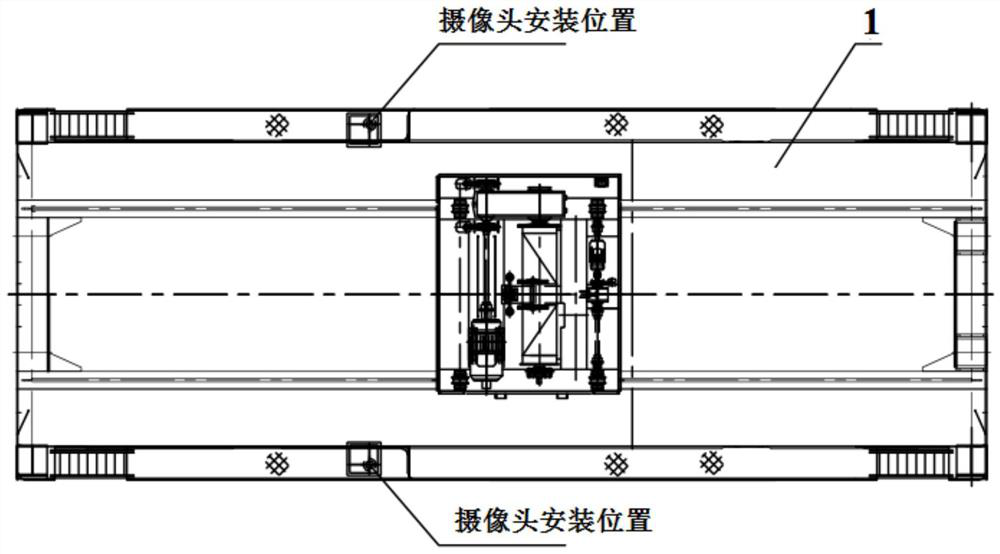
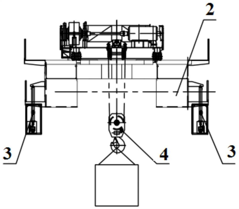
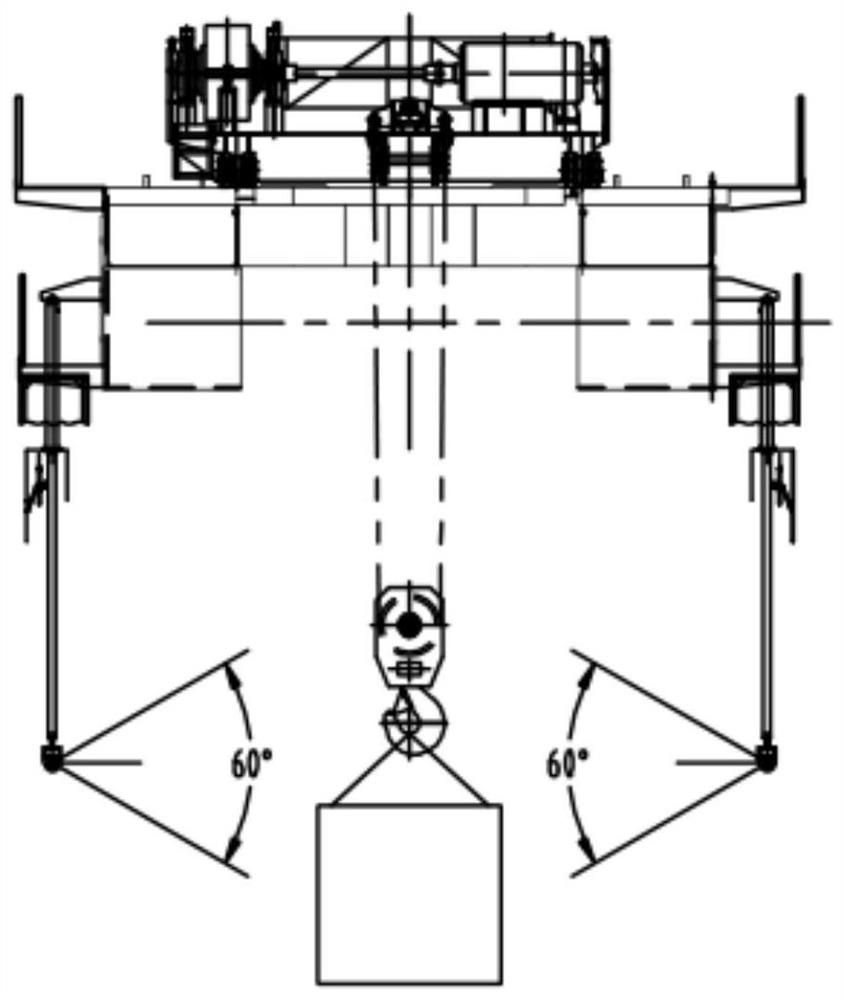
[0036] see Figures 1 to 6 , shows a camera displacement changing device 3 for a bridge crane 1 according to an embodiment of the present invention, wherein the crane 1 includes a hook 4, a c...


PUM


Abstract

The invention discloses a camera displacement changing device for a bridge crane, which is suitable for being installed on both sides of the crane's hook and suspended under the steel structure of the main girder of the crane, wherein the camera displacement changing device includes: A camera assembly, which includes two cameras; a telescopic device assembly for vertically lifting the camera assembly, which includes two telescopic devices, each telescopic device includes a telescopic rod and a fixed jacket, and the lower ends of each telescopic rod are connected to corresponding The camera can move vertically together with the corresponding camera; the sealing assembly that can be opened and closed includes two sealing devices, and each sealing device includes a protective cover, an openable bottom plate, and a lifting assembly hinged to the bottom plate. The present invention can meet the angle of view requirements of intelligent or unmanned cranes for video monitoring by adding camera displacement changing devices on both sides of the crane, and also has the function of dustproof and rainproof, which can meet the harsh working conditions of open air and dusty environment use below.

Description

technical field [0001] The invention relates to the technical field of cranes, in particular to a camera displacement changing device for bridge cranes. Background technique [0002] With the development of intelligent and unmanned bridge cranes, the demand for image monitoring and image recognition technology during crane operation and hoisting is also increasing. However, the bridge crane is generally located in the upper part of the workshop, and the heavy objects to be lifted are below its running path. In order to monitor the heavy objects to be lifted, it also meets the image requirements of some special cranes, such as casting cranes for molten iron The decoupling recognition of bales, the decoupling recognition of steel coils by clamp cranes, etc., are traditionally used to install cameras on cranes, but this is often difficult to meet the viewing angle, especially the viewing angle requirements of image recognition technology. [0003] Therefore, there is a need in...

Claims


Application Information

Patent Timeline
Patent Type & Authority Patents(China)
IPC IPC(8): B66C13/16F16M11/04F16M13/02
CPCB66C13/16F16M11/046F16M13/02
Inventor 朱东科顾翠云熊良勇刘大淮李军顾红泽周继红周亮亮申昌宏
Owner TAIYUAN HEAVY IND
Learn More