
Scalpel blade detacher

A disassembler and scalpel technology, which is applied in the direction of dissection instruments, can solve problems such as cuts, and achieve the effect of eliminating infection, convenient and quick disassembly, and simple and easy-to-use disassembly mechanism

Pending Publication Date: 2020-05-12
自贡市第一人民医院
View PDF0 Cites 1 Cited by
  • Summary
  • Abstract
  • Description
  • Claims
  • Application Information

AI Technical Summary

Problems solved by technology

During operation, the operator is at risk of being cut by the sharp blade 10

Method used


Image

  • Scalpel blade detacher
  • Scalpel blade detacher
  • Scalpel blade detacher

Examples


Embodiment Construction

[0020] In order to enable those skilled in the art to better understand the technical solutions of the present invention, the present invention will be further described in detail below in conjunction with specific embodiments.

[0021] Such as Figure 4-Figure 6 As shown, the present invention includes a remover body 1, which is provided with a blade groove 2 for the blade 10 to penetrate and a tang groove 3 for the shank 12 tang 13 to penetrate on the said remover body 1; the blade groove 2 It intersects with the section of the tang groove 3 in a cross shape. Preferably, the upper part of the tang groove 3 intersects with the middle part of the blade groove 2 . The bottom of the blade groove 2 is located on the left and right sides of the tang groove 3 and is respectively provided with a board 4, and the board 4 can slide back and forth along the blade groove 2; the bottom of the tang groove 3 is provided with a flap 5, so The distal end of the turnover plate 5 is movably ...


PUM


Abstract

The invention discloses a scalpel blade detacher. The scalpel blade detacher comprises a detacher body, wherein a blade groove for a blade to penetrate and a handle foot groove for a handle foot of ascalpel handle to penetrate are formed in the detacher body; and the sections of the blade groove and the handle foot groove are crossed. According to the scalpel blade detacher with the structure, the blade groove is used for clamping the blade and then the scalpel handle is turned over to achieve a purpose of detaching the blade. The detaching manner is convenient and rapid and a detaching mechanism is simple and easy to use. When the scalpel blade detacher is used, a doctor does not need to hold the blade with hands, thus, the doctor is prevented from being cut by the blade, and the hiddendanger of infection of medical workers is eliminated.

Description

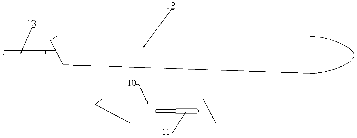
technical field [0001] The invention relates to a device for removing a scalpel blade from a handle. Background technique [0002] Such as figure 1 , figure 2 , image 3 As shown, a conventional scalpel generally includes a reusable, sterilizable elongated handle 12 on which a replaceable blade 10 having a longitudinal groove 11 can be secured. The far-end place of handle of a knife 12 is tang 13, and tang 13 side walls are engraved with chute. When assembling, the tang goes through the groove of the blade, and the narrowed part of the groove is embedded in the slide groove on the side wall of the tang, so that the assembly is stable. [0003] The handle 12 is used repeatedly, but the blade 10 is usually discarded after one use, either because the blade 10 becomes dull or contaminated, or because another style of blade 10 is required. In order to remove the blade 10 from the handle 12, the part of the rear of the tang 13 that is not engraved with the slide groove must ...

Claims


Application Information

Patent Timeline
Patent Type & Authority Applications(China)
IPC IPC(8): A61B17/3213A61B17/3217
CPCA61B17/3213A61B17/3217
Inventor 罗莉郭水英颜琪刘伟男江英罗丽娜吴红英曾祥兵黄伟柳凯
Owner 自贡市第一人民医院
Learn More