Eureka AIR delivers breakthrough ideas for toughest innovation challenges, trusted by R&D personnel around the world.

Air bearing

An air bearing and shaft technology, applied in the field of bearings, can solve the problems of rotor speed drop, rotor and bearing collision, danger, etc., and achieve the effect of maintaining stability, reducing flow and power consumption

Pending Publication Date: 2020-05-08
刘慕华
View PDF0 Cites 1 Cited by
  • Summary
  • Abstract
  • Description
  • Claims
  • Application Information

AI Technical Summary

Problems solved by technology

When the speed of the gas turbine rotor system exceeds 40,000 RPM (revolutions per minute), ordinary mechanical bearings can no longer meet the requirements of the working speed. Therefore, the existing technology proposes to use non-contact bearings to replace the original mechanical bearings. Among them, the most representative for air bearings
[0003] However, the air bearings in the prior art have the following defects: when the air bearing is just started, the air between the bearing and the rotor is in a compressed state, and there is pressure. When the natural frequency is the same, it will cause resonance. If the resonance is mild, the system noise and vibration will be serious, and if the resonance is serious, the parts will be scrapped.
Therefore, when the static pressure air supply is turned off or the static pressure air supply pipe is directly unplugged, there will be a sudden change in the pressure of the gas film at the orifice, and the gas film will be discontinuous, and the gas will tend to release the pressure through the orifice, while It is not squeezed in the bearing gap, so the bearing capacity is reduced, the position of the rotor in the bearing is lowered, and the lower edge of the rotor will be closer to the inner edge of the bearing, which is prone to collision
[0006] In addition, the orifice will generate additional interference force due to the entry and exit of gas, which will interfere with the stability of the gas film inside the bearing and easily lead to bearing instability, resulting in collision between the rotor and the bearing, causing the rotor speed to drop or even stop directly.
However, the contact between the high-speed rotor and the bearing is very dangerous, which can cause the bearing rotor to be scrapped on the spot

Method used


Image

  • Air bearing
  • Air bearing
  • Air bearing

Examples


Embodiment Construction

[0050] In order to better understand the technical solutions of the present invention, the present invention will be further described below in conjunction with specific embodiments and accompanying drawings.

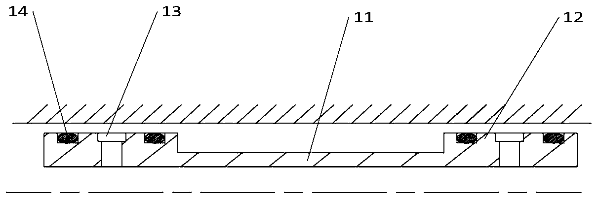
[0051] The present invention provides a side-by-side air bearing with an orifice, such as figure 1 As shown, it is an embodiment of an orifice setting, which includes a cylindrical body 11, and a plurality of concentric ring-shaped damping seats 12 are integrally formed on the periphery of one end of the body 11, and dampers 14 are installed radially on the damping seats 12. The seat 12 is radially provided with a mounting groove matching the damper 14 , and the damper seat 12 is provided with a throttle hole 13 passing through the body 11 in the radial direction. The part of the main body 11 with the damping seat 12 and the orifice 13 is the static pressure part of the air bearing, and the part of the main body 11 without the damping seat 12 and the orifice 13 is the d...


PUM


Abstract

The invention provides an air bearing. The air bearing is used for being mounted on a rotating shaft and comprises a cylindrical body, a plurality of concentric annular damping seats are integrally formed on the periphery of the end of the body, dampers are radially mounted on the damping seats, the damping seats are radially provided with mounting grooves matched with the dampers, the dampers areeach in an elastic O-shaped ring form, O-shaped rings are circumferentially arranged in the mounting grooves in a sleeved mode and are higher than the mounting grooves, and throttle holes penetratingthrough the body in the radial direction are formed among the damping seats. Through the few number of small-diameter throttle holes, the air bearing can maintain a good static pressure load as well.

Description

technical field [0001] The invention relates to the technical field of bearings, in particular to an air bearing. Background technique [0002] The micro gas turbine is a newly developed small heat engine, its stand-alone power ranges from 25 to 300kW, and its basic technical features are radial flow impeller machinery and regenerative cycle. A micro gas turbine generator set usually consists of a coaxially mounted generator and a micro gas turbine. Specifically, a micro gas turbine mainly includes three major components: a compressor, a combustion chamber and a turbine. After the air enters the compressor, it is compressed into high-temperature and high-pressure air, which is then supplied to the combustion chamber for mixed combustion with fuel. The high-temperature and high-pressure gas generated expands in the turbine to do work, driving the turbine to rotate, and the turbine then drives the generator to generate electricity. When the speed of the gas turbine rotor sys...

Claims


Application Information

Patent Timeline
Patent Type & Authority Applications(China)
IPC IPC(8): F16C17/00F16C32/06
CPCF16C17/00F16C32/0614
Inventor 刘慕华
Owner 刘慕华
Why Eureka
Eureka Blog
Learn More