Horizontal scroll compressor for vehicle and pump body assembly thereof

A scroll compressor and pump body technology, which is applied in the field of compressors, can solve the problems of increasing the overall noise of the compressor, increasing the complexity of compressor assembly and manufacturing costs, and the number of parts, so as to reduce the complexity of assembly , Realize anti-rotation function and reduce the number of parts

Pending Publication Date: 2020-05-08
SHANGHAI HIGHLY NEW ENERGY TECH CO LTD
View PDF0 Cites 0 Cited by
  • Summary
  • Abstract
  • Description
  • Claims
  • Application Information

AI Technical Summary

Problems solved by technology

[0003] First, the lubrication conditions between the anti-rotation pin and the slip ring are relatively harsh. In the case of frequent start-up and stop of the compressor, and starting after a long period of standby, there is not enough lubricating oil between the anti-rotation pin and the slip ring, resulting in serious wear , affecting the life of the compressor;
[0004] Second, the contact between the anti-rotation pin made of metal material and the sliding line of the slip ring produces a large noise, which increases the noise of the compressor;
[0005] Third, the coordination between the anti-rotation pin and the slip ring is highly demanding, and the number of parts is large, which increases the complexity of compressor assembly and manufacturing costs

Method used


Image

  • Horizontal scroll compressor for vehicle and pump body assembly thereof
  • Horizontal scroll compressor for vehicle and pump body assembly thereof
  • Horizontal scroll compressor for vehicle and pump body assembly thereof

Examples


Embodiment Construction

[0028] Example embodiments will now be described more fully with reference to the accompanying drawings. Example embodiments may, however, be embodied in many forms and should not be construed as limited to the embodiments set forth herein. Rather, these embodiments are provided so that this disclosure will be thorough and complete, and will fully convey the concept of the example embodiments to those skilled in the art. The same reference numerals denote the same or similar structures in the drawings, and thus their repeated descriptions will be omitted.

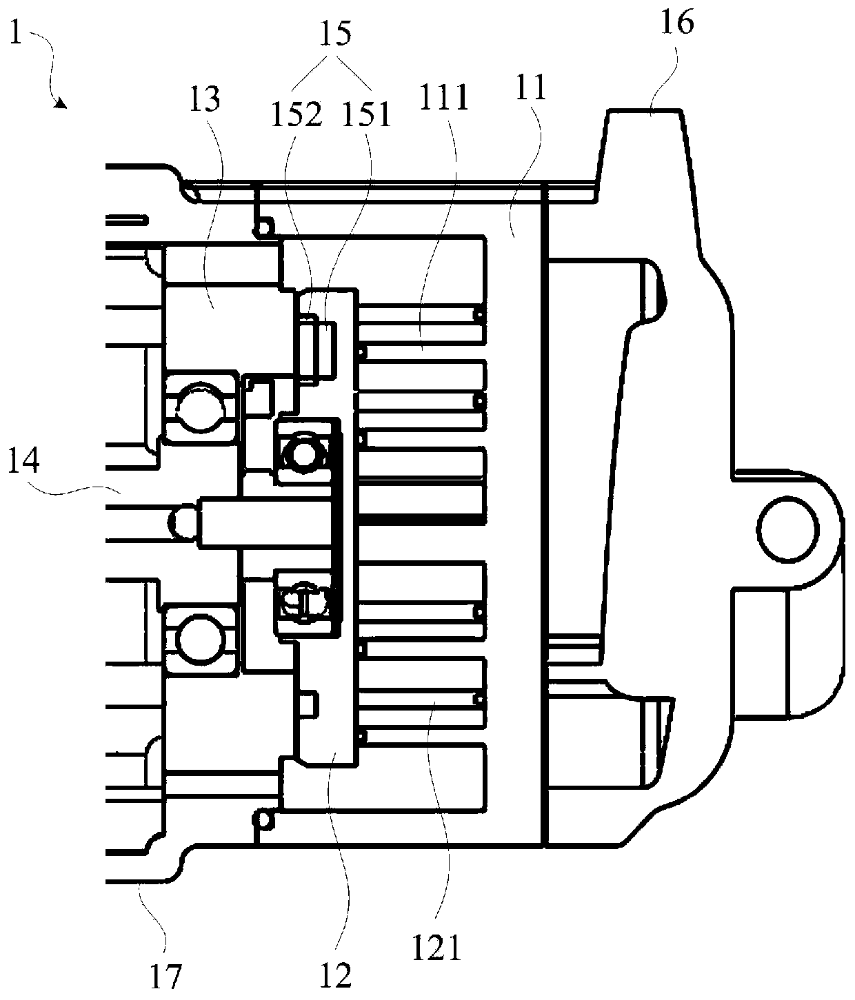
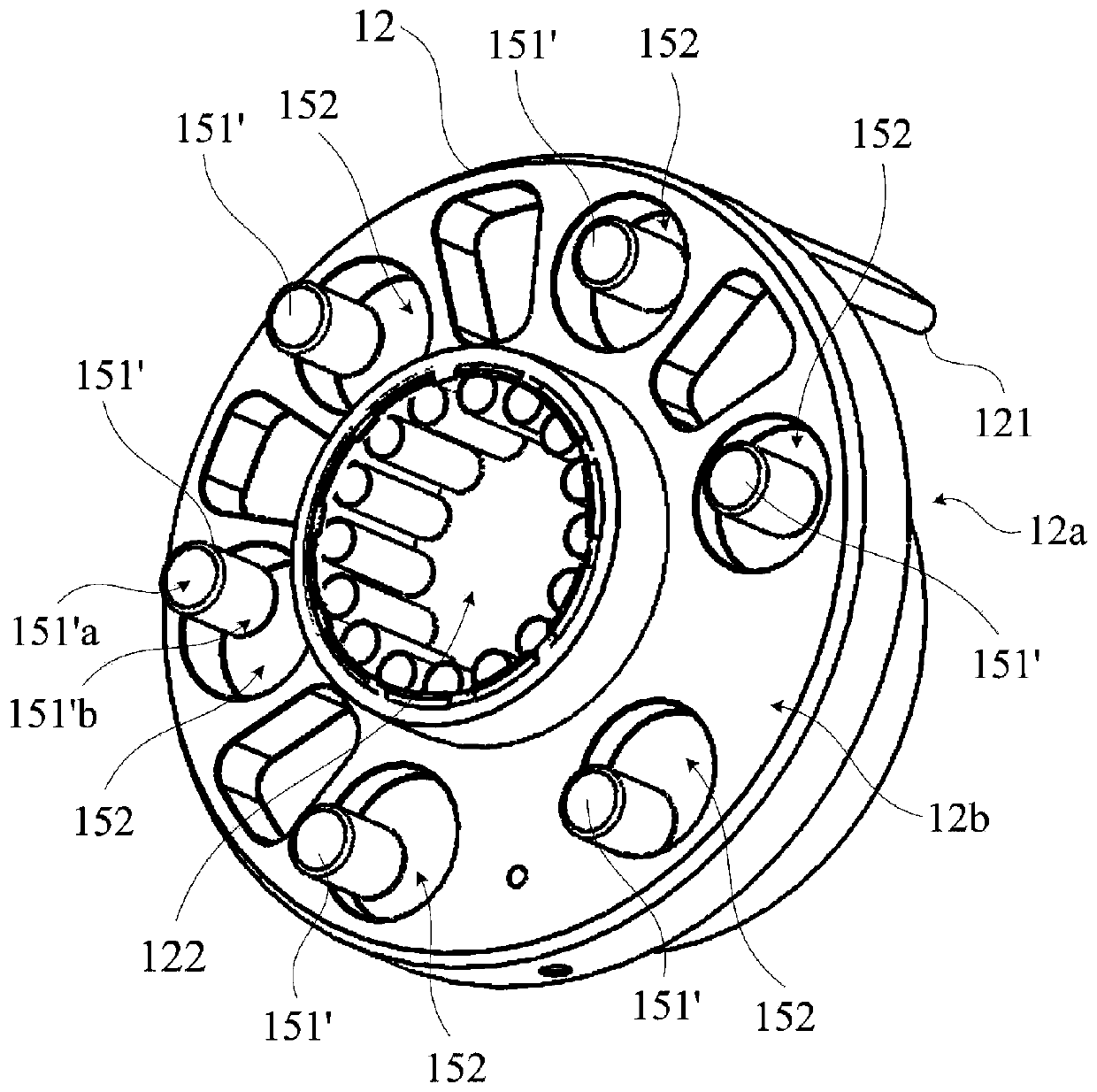
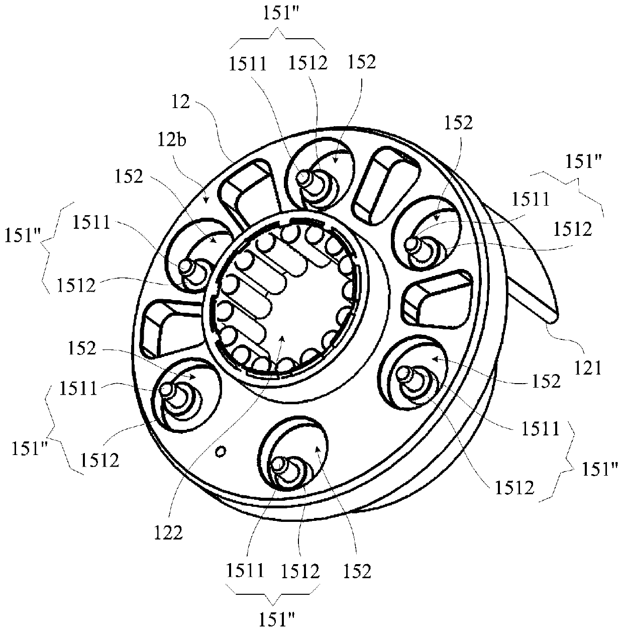
[0029] figure 1 The partial cross-sectional structure of the horizontal scroll compressor for vehicles in the embodiment is shown, including the main structure of the pump body assembly. refer to figure 1 As shown, the pump body assembly of the horizontal scroll compressor 1 for vehicles mainly includes a fixed scroll 11 with a fixed scroll 111, a movable scroll 12 with a rotating scroll 121 that cooperates with the fixe...


PUM


Abstract

The invention relates to the technical field of compressors and provides a horizontal scroll compressor for a vehicle and a pump body assembly thereof. The pump body assembly comprises a stationary vortex plate provided with a fixed scroll, a movable vortex plate provided with a rotating screen forming a working cavity with the fixed scroll, a bracket supported on the back surface of the movable vortex plate and an eccentric crankshaft which is arranged in an axle hole of the movable vortex plate in a penetrating manner. The pump body assembly also comprises a plurality of groups of anti-rotation mechanisms which are circumferentially arranged between the movable vortex plate and the bracket in a spaced manner, the anti-rotation mechanisms are formed by pin structures stretching into roundholes, and the pin structures are in tangential fit with the round holes to limit circumferential rotation of the movable vortex plate; the pin structures are mounted on the end surface of the bracket, and the round holes are formed in the back surface of the movable vortex plate; or the pin structures are mounted on the back surface of the movable vortex plate and the round holes are formed in the end surface of the bracket. By matching the pin structures mounted on the back surface of the movable vortex plate or the end surface of the bracket with the round holes directly formed in the endsurface of the bracket or the back surface of the movable vortex plate tangentially, an anti-rotation function of the movable vortex plate is achieved. The horizontal scroll compressor is high in reliability and convenient to match, and noise and cost can be reduced.

Description

technical field [0001] The invention relates to the technical field of compressors, in particular to a horizontal scroll compressor for vehicles and a pump body assembly thereof. Background technique [0002] The horizontal scroll compressor for vehicles is installed in the air-conditioning system of the vehicle for cooling and heating of the vehicle. At present, an anti-rotation mechanism with anti-rotation pins and slip rings is widely used in horizontal scroll compressors for vehicles. The anti-rotation pin is installed on one mating part of the compressor, and the slip ring is installed in the opening of the other mating part. During the working process of the compressor, the anti-rotation pin is in contact with the sliding line of the slip ring, which will cause the following problems. [0003] First, the lubrication conditions between the anti-rotation pin and the slip ring are relatively harsh. In the case of frequent start-up and stop of the compressor, and startin...

Claims


Application Information

Patent Timeline
Patent Type & Authority Applications(China)
IPC IPC(8): F04C18/02F04D29/00F04C29/06
CPCF04C18/0223F04C29/06F04C2240/805F04D29/00
Inventor 黄志刚朱浩立牟英涛曲冬琦
Owner SHANGHAI HIGHLY NEW ENERGY TECH CO LTD
Why Eureka
Try Eureka