Engine oil-gas separation device and engine

A separation device, oil and gas separation chamber technology, applied in the direction of engine components, machines/engines, mechanical equipment, etc., can solve problems such as unfavorable condensed lubricating oil backflow, to facilitate condensed lubricating oil backflow, increase contact or collision area, reduce effect of risk

Active Publication Date: 2022-06-03
CHONGQING LONCIN MOTOR +1
View PDF7 Cites 0 Cited by
  • Summary
  • Abstract
  • Description
  • Claims
  • Application Information

AI Technical Summary

Problems solved by technology

The general design principle of the oil-gas separation labyrinth is to design a labyrinth structure on the discharge path of the oil-gas (lubricating oil and gas) mixture to increase the contact or collision area between the oil-gas mixture and the labyrinth path, so that the lubricating oil can condense and flow back; but the mixed flow of the labyrinth design The flow direction and condensate return flow interfere with each other inside the labyrinth, which is not conducive to the return flow of condensate lubricating oil

Method used


Image

  • Engine oil-gas separation device and engine
  • Engine oil-gas separation device and engine
  • Engine oil-gas separation device and engine

Examples


Embodiment Construction

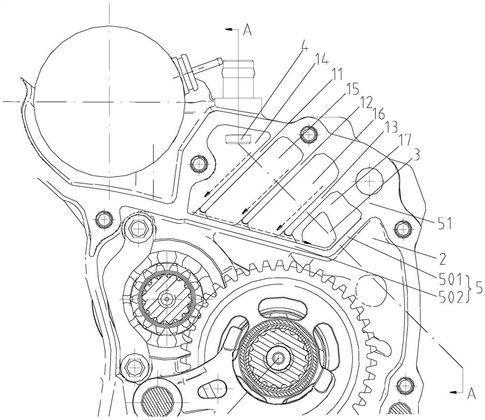
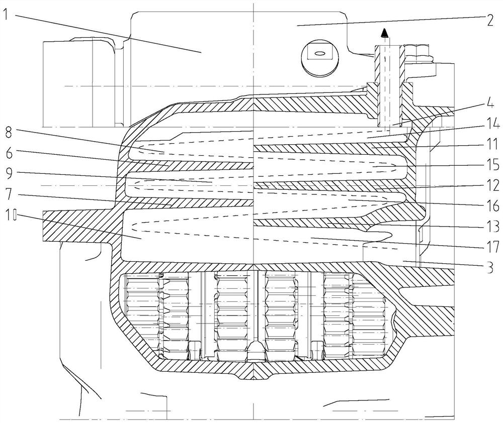
[0019] figure 1 is a schematic diagram of the structure of the present invention, figure 2 It is a schematic diagram of the structure in the A-A direction after the left and right crankcase bodies of the present invention are closed. As shown in the figure: the engine oil-gas separation device and the engine of the present embodiment include a partition plate 5 connected to the crankshaft chamber, the partition plate 5 isolates the oil-gas separation chamber from the crankcase, and the oil-gas separation chamber is provided with There is a labyrinth passage, and the oil and gas separation chamber is also provided with an air inlet 3 that communicates with the inlet end of the labyrinth passage and an exhaust port 4 that communicates with the exhaust end of the labyrinth passage. The air inlet 3 is located in the oil and gas separation chamber. bottom. The intake port 3 is connected to the exhaust port of the crankcase, and the exhaust port 4 is connected to the intake port ...


PUM


Abstract

The invention discloses an engine oil-gas separation device and an engine, comprising an isolation plate connected to the crankshaft chamber, the isolation plate isolates an oil-gas separation chamber from the crankcase, a labyrinth channel is arranged in the oil-gas separation chamber, and the oil-gas The separation chamber is also provided with an air inlet connected to the inlet end of the labyrinth channel and an exhaust port connected to the exhaust end of the labyrinth channel, and the air inlet is located at the bottom of the oil-gas separation chamber. The arrangement of the labyrinth channel can increase the contact or collision area of ​​the gas flow path of the oil-air mixture, so as to facilitate the condensation of liquid substances. The air inlet is not only the import port of the oil-gas mixture, but also the return port of the condensed liquid substance after the oil-gas mixture is separated, which reduces the number of return ports opened in the oil-gas separation chamber and reduces the time-divided path of the oil-gas mixture flowing in the oil-gas separation chamber. Risk of returning to the crankcase through the return port.

Description

technical field [0001] The invention relates to the field of engines, in particular to an engine oil and gas separation device and an engine. Background technique [0002] Existing two-wheel and three-wheel gasoline engines have the following technical disadvantages: a piston reciprocating engine, due to the reciprocating motion of the piston and the characteristics of a small amount of blow-by gas at the piston, its crankcase must be designed with an engine breathing system (or oil-gas separation system), the purpose of which is Separating the oil-air mixture discharged from the crankcase, allowing the lubricating oil to condense and return, extending the service life of the lubricating oil. When the engine is working, a part of the high temperature and high pressure gas leaks into the crankcase through the piston ring. If this part of the gas is not discharged in time, the lubricating oil will be thinned and the performance will be deteriorated. After installing the oil an...

Claims


Application Information

Patent Timeline
Patent Type & Authority Patents(China)
IPC IPC(8): F01M13/04
CPCF01M13/04F01M2013/0461
Inventor 王良陈志敏周良兵刘智江刘建文
Owner CHONGQING LONCIN MOTOR
Why Eureka
Try Eureka