An artificial intelligence automatic obstacle avoidance walking chassis
An automatic obstacle avoidance and artificial intelligence technology, applied in non-electric variable control, instruments, control/regulation systems, etc., can solve problems such as large mass, inconvenience to move into the workshop, scratches, etc.
- Summary
- Abstract
- Description
- Claims
- Application Information
AI Technical Summary
Problems solved by technology
Method used
Image
Examples
Embodiment 1
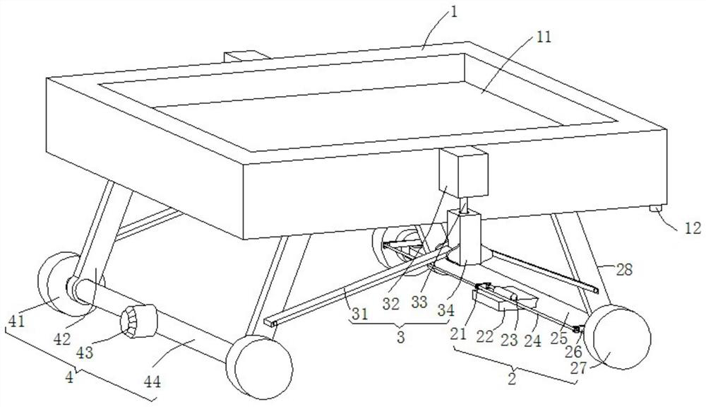
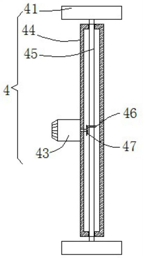
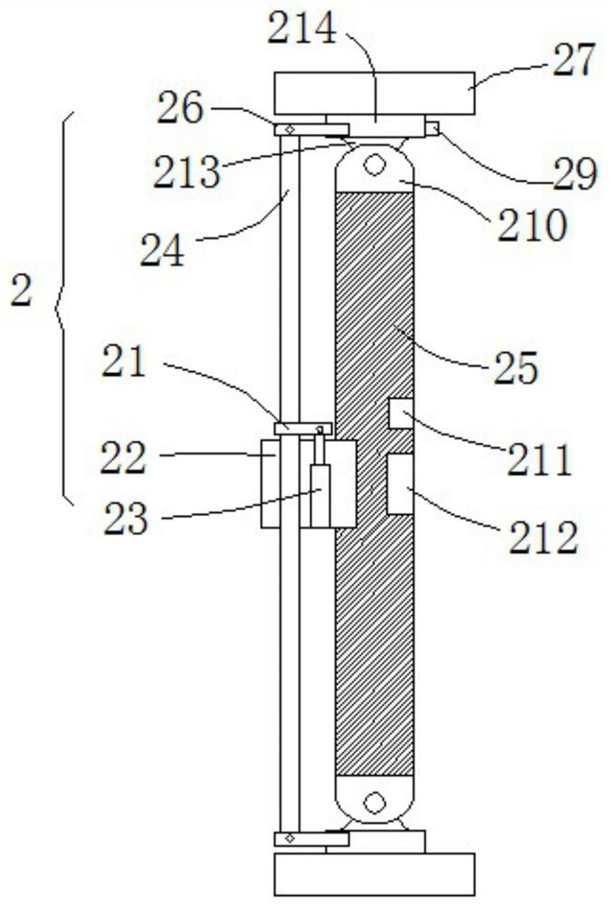
[0030] see Figure 1-5 , this embodiment provides an artificial intelligence automatic obstacle avoidance walking chassis, including a chassis 1, a data processing module 5, a driving mechanism 4, a steering mechanism 2 and two adjustment mechanisms 3, and the driving mechanism 4 includes two first hinged rods 42. The first rotating sleeve 44, the driving motor 43 and the two power wheels 41. The top surfaces of the two first articulated rods 42 of the driving mechanism 4 are respectively hinged on the front and rear sides of the left end of the bottom surface of the chassis 1. The steering mechanism 2 includes There are two second articulated rods 28, a second rotating sleeve 25, an electric hydraulic cylinder 23, a transmission rod 24 and two steering wheels 27, and the top surfaces of the two second articulated rods 28 of the steering mechanism 2 are respectively hinged on the chassis 1 The two adjustment mechanisms 3 include a servo motor 32, a threaded rod 33, a rectangul...
Embodiment 2
[0036] see Figure 1-5 , further improvements have been made on the basis of Example 1:
[0037] The top surface of the chassis 1 is provided with a rectangular placement groove 11. By opening the rectangular placement groove 11, it is convenient to match the bottom corner side wall of the receiving equipment, so as to facilitate the auxiliary movement of the equipment;
Embodiment 3
[0039] see Figure 1-5 , further improvements have been made on the basis of Example 1:
[0040] Each servo motor 32 is respectively connected with each threaded rod 33 through a power shaft, and each rectangular lifting seat 34 is provided with a threaded hole running through the upper and lower end faces of the rectangular lifting seat 34, and each threaded rod 33 is connected with each rectangular lifting seat through external threads respectively. The threaded hole inner cavity of seat 34 is rotated and plugged in, and the left and right end surface bottoms of each rectangular lifting seat 34 are hinged with the tops of two pull rods 31 respectively, and the tips of two pull rods 31 are respectively connected with the first hinged rod 42 and the second hinged rod. The bottom of the outer wall of 28 is hinged; the bottom end face of the chassis 1 is embedded with a height sensor 12 in the right front face, and the signal output port of the height sensor 12 is connected with...
PUM
 Abstract
Description
Claims
Application Information
 - R&D Engineer
- R&D Manager
- IP Professional
- Industry Leading Data Capabilities
- Powerful AI technology
- Patent DNA Extraction
Browse by: Latest US Patents, China's latest patents, Technical Efficacy Thesaurus, Application Domain, Technology Topic, Popular Technical Reports.
© 2024 PatSnap. All rights reserved.Legal|Privacy policy|Modern Slavery Act Transparency Statement|Sitemap|About US| Contact US: help@patsnap.com


