A Dynamic Calibration Method for Accelerator Pedal Position of Potentiometer

A technology for the position and dynamic calibration of the accelerator pedal, which is applied in the layout of the power unit control mechanism, the measurement device, and the test of the vehicle. The effect of good performance, low compensation accuracy and precise accelerator pedal position

Active Publication Date: 2021-06-04
XIAN AVIATION COMPUTING TECH RES INST OF AVIATION IND CORP OF CHINA
View PDF5 Cites 0 Cited by
  • Summary
  • Abstract
  • Description
  • Claims
  • Application Information

AI Technical Summary

Problems solved by technology

[0004] Aiming at the problem that the improved potentiometer has poor anti-interference and the traditional control method cannot accurately measure the entire accelerator pedal in the range from zero accelerator to full-scale accelerator, this invention proposes a new calculation method for accelerator pedal control. Based on the calibration of the zero position, the control process of the full scale position is added, and the calibration process is extended to the full working cycle of the electronic control system to improve the control calculation accuracy of the accelerator pedal and to overcome the low accuracy of the potentiometer. , Poor anti-interference, resulting in the inability to accurately measure the entire accelerator pedal in the range from zero throttle to full scale throttle

Method used


Image

  • A Dynamic Calibration Method for Accelerator Pedal Position of Potentiometer
  • A Dynamic Calibration Method for Accelerator Pedal Position of Potentiometer

Examples


Embodiment Construction

[0025] The method of the present invention is illustrated below by specific examples. What this example uses is a six-cylinder heavy truck engine electronic controller, which includes an accelerator pedal control unit to be tested. The implementation steps are as follows:

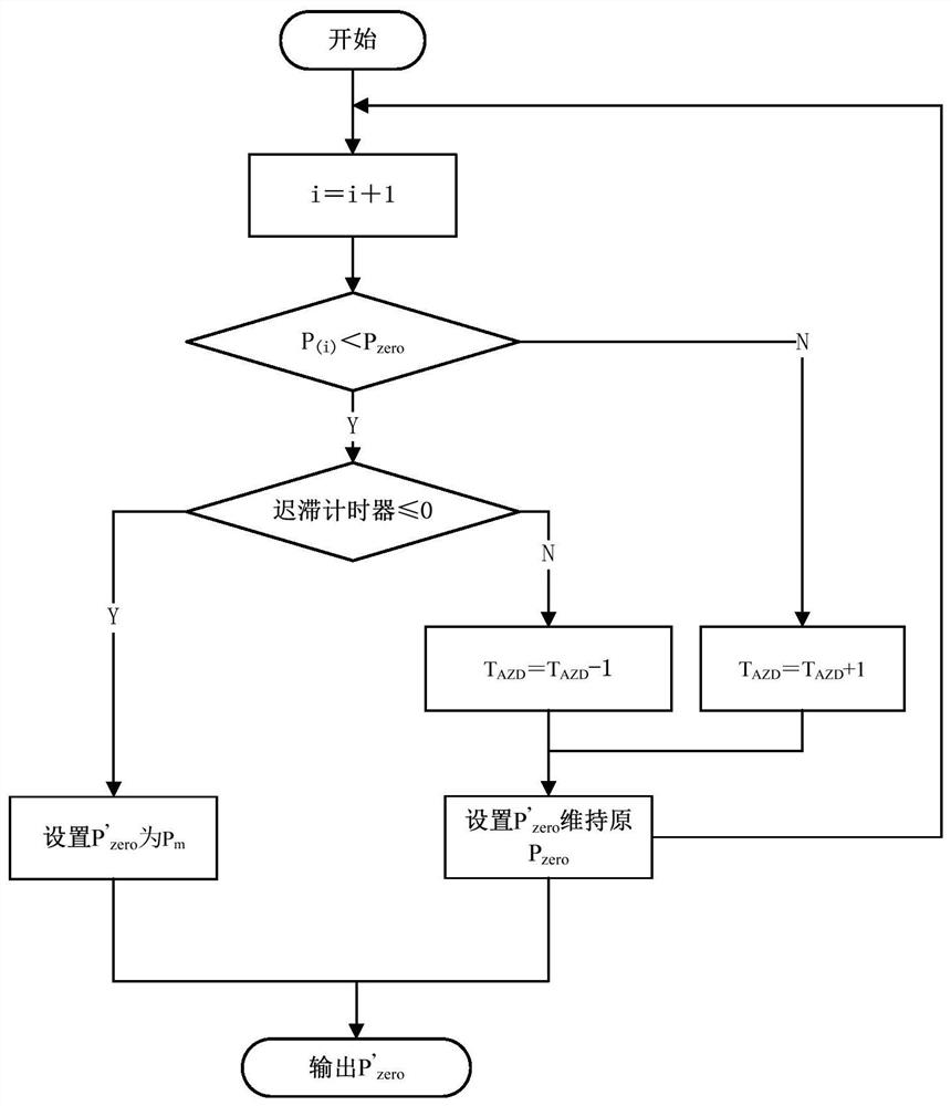
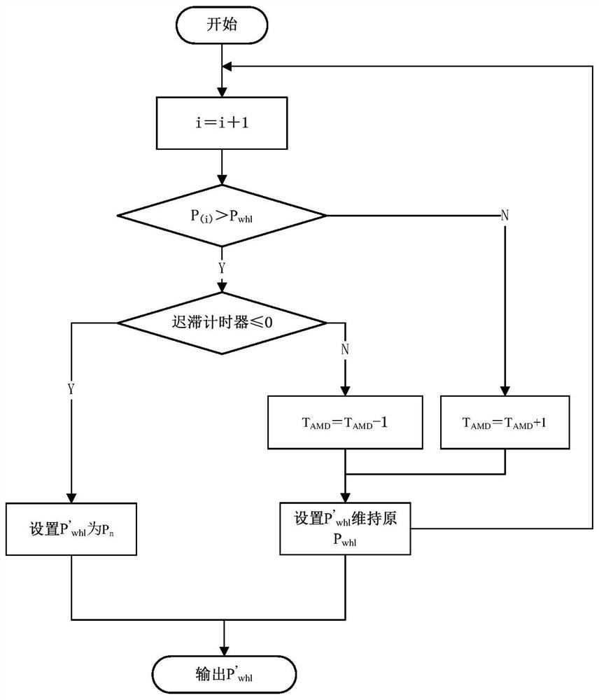
[0026] Step 1: Determine the zero range value T corresponding to the potentiometer when calibrating the throttle zero position according to the characteristics of the potentiometer before installation PZ The full-scale value T corresponding to the potentiometer is 26% and the throttle is full-scale PW is 89%; set the first-order linear filter coefficient C FLTR =0.15; zero calibration delay T AZD 500ms, full scale bit calibration delay T AMD 500ms;

[0027] Step 2: After the car is started, according to the calibrated zero range value T PZ Set current throttle zero position P zero , while according to the calibrated full-scale value T PW Set the current full throttle position P whl ;

[0028] Step 3...


PUM


Abstract

The invention discloses a dynamic calibration method for the position of a potentiometer accelerator pedal, which belongs to the field of vehicle power control. The traditional static pure zero calibration method is improved, which overcomes the problem that the potentiometer has low precision and poor anti-interference, which leads to the inability to accurately measure the entire accelerator pedal from the zero-position accelerator to the full-scale accelerator. The main steps of the method are: 1. Calibrate the zero position range value and the full scale position value; 2. Determine the current throttle zero position and the current throttle full scale position P when the car starts whl 3. Periodic collection of throttle signal; 4. Zero calibration process; 5. Full-scale calibration process; 6. Calculate the current throttle position sequence value; 7. Determine the actual output throttle position.

Description

technical field [0001] The invention belongs to the technical field of electric control engine power control. Specifically, it is a method for judging the position of a potentiometer accelerator pedal on an electronically controlled power control vehicle. Background technique [0002] The gas pedal is one of the most important signal input devices in a car, and the driver controls the acceleration characteristics of the vehicle through the gas pedal. The position of the accelerator pedal is usually controlled by the installed potentiometer position sensor on the current electric control vehicle. This kind of sensor reflects the change of position through the change of voltage. The voltage and position have a linear correspondence, which is convenient for calculation. Moreover, the space required for installation of this type of sensor is small, and two channels can be installed at the same time for redundant control in a limited space. But its disadvantage is that the accu...

Claims


Application Information

Patent Timeline
Patent Type & Authority Patents(China)
IPC IPC(8): B60K26/02G01M17/007G01M13/00
CPCB60K26/02B60K2026/026G01M13/00G01M17/007
Inventor 王瑞毛宁谭琪璘马振华梁欣颖王旭昊
Owner XIAN AVIATION COMPUTING TECH RES INST OF AVIATION IND CORP OF CHINA
Why Eureka
Try Eureka