
An in-orbit 3D printer

A 3D printer and print head technology, applied in 3D object support structures, coating devices, manufacturing tools, etc., can solve problems such as increased launch costs, 3D size limitations, losses, etc., to reduce transportation costs, ensure service life, The effect of good surface quality

Active Publication Date: 2022-03-04
佛山中国空间技术研究院创新中心
View PDF0 Cites 0 Cited by
  • Summary
  • Abstract
  • Description
  • Claims
  • Application Information

AI Technical Summary

Problems solved by technology

[0003] At present, the manufacturing scheme adopted by large-diameter truss structures in the world is generally "ground manufacturing, retracted launch, and on-orbit deployment and assembly". However, this manufacturing scheme is limited by the size of the launch vehicle, and it is difficult to realize the launch of super large truss
In space, the truss bears very little force, and the structural strength can be weak, but in order to withstand the large overload conditions during rocket launch, the folded truss must have great strength, resulting in an increase in the structural weight, which greatly increases the launch cost
Due to the large deployment ratio of the truss, the structure is often very complicated, and failures often occur during deployment, causing great losses
[0004] In addition, the additive manufacturing equipment currently on the market has restrictions on the three-dimensional dimensions of the manufactured workpieces, and is not suitable for the manufacture of ultra-long rods in trusses

Method used


Image

  • An in-orbit 3D printer
  • An in-orbit 3D printer
  • An in-orbit 3D printer

Examples


Embodiment Construction

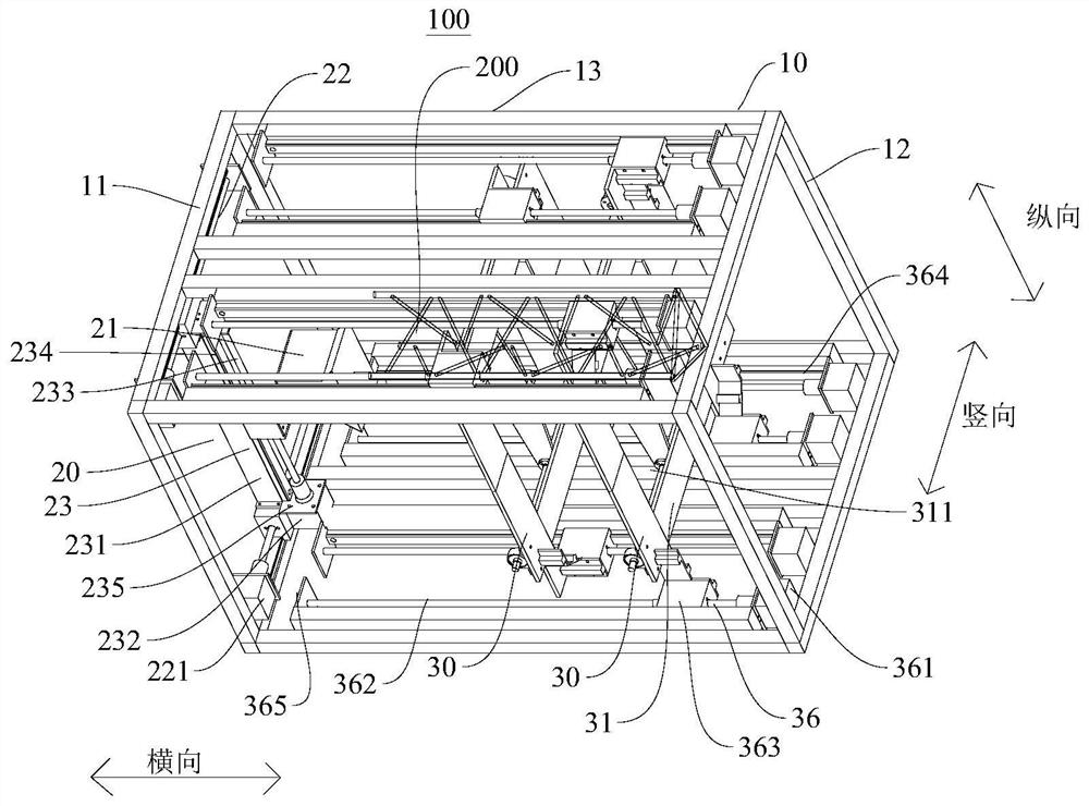
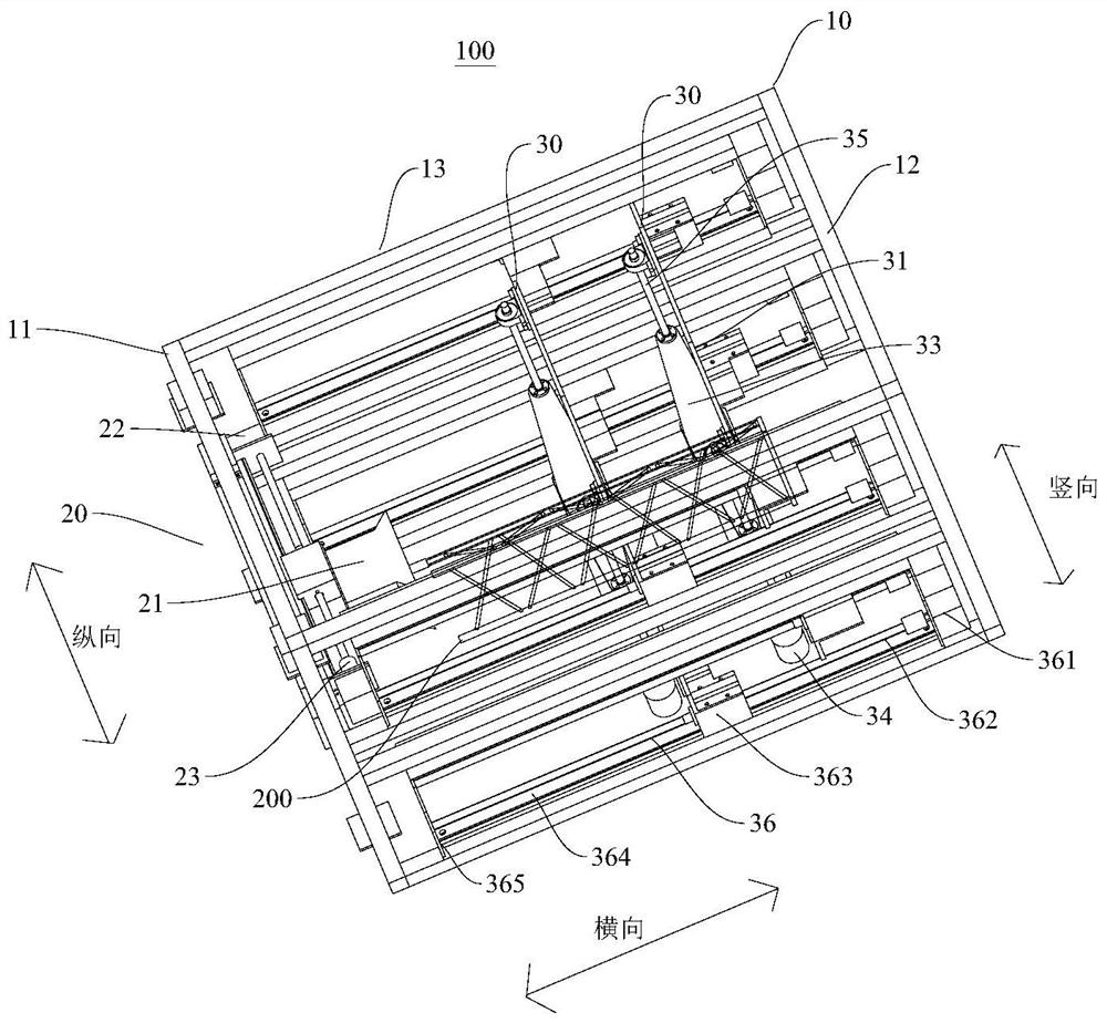
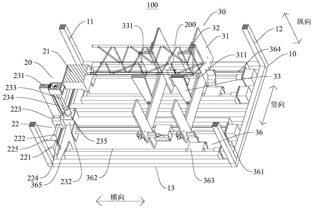
[0046] Refer below Figure 1-Figure 5 An on-orbit 3D printer 100 according to an embodiment of the present invention is described. The on-orbit 3D printer 100 can realize on-orbit printing of a truss structure, wherein the on-orbit refers to the space environment, which is different from the ground.

[0047] Such as Figure 1 ~ Figure 3 As shown, the on-rail 3D printer 100 according to the embodiment of the present invention includes: a frame 10, a spraying device 20 and two clamping devices 30, the spraying device 20 and the two clamping devices 30 are all arranged on the frame 10, and the frame 10 can Play the role of installation and protection. The two clamping devices 30 can cooperate with each other, so as to ensure the stability of their clamping of the printed part 200 .

[0048] Such as figure 1 and figure 2 As shown, the frame 10 is composed of a plurality of rod connections, wherein the frame 10 has a first bracket 11 and a second bracket 12 opposite in the lat...


PUM


Abstract

The invention discloses an on-rail 3D printer, comprising: a frame, the frame has a first support and a second support opposite in the transverse direction; a spraying device, the spraying device is arranged on the first support, and the spraying device includes a printing head, a second support A vertical motor and a vertical motor, the first vertical motor is used to drive the print head to move vertically, the vertical motor is used to drive the print head to move vertically, the print head includes a wire feeding motor; the clamping device, the clamping device can move horizontally Set on the frame and between the first bracket and the second bracket; the first processor, the first vertical motor, and the vertical motor are connected to the first processor; the second processor, the wire feeding motor and the second processor connected, wherein the first processor is connected to the second processor. The present invention can realize the effective printing of the printing head through the coordination and cooperation of the first processor and the second processor, and can obtain better surface quality of the printed parts. The invention can be widely applied in the field of printers.

Description

technical field [0001] The invention relates to the technical field of printers, in particular to an on-rail 3D printer. Background technique [0002] The truss structure is the basic structure of large-scale space equipment—such as the main structure of the International Space Station, the double-satellite interferometric SAR connection structure, and the large-aperture satellite antenna. It is more likely to be the basic structure of large-scale facilities in orbit in the future. one of the key points. [0003] At present, the manufacturing scheme adopted for large-diameter truss structures in the world is generally "ground manufacturing, retracted launch, and in-orbit deployment and assembly". However, this manufacturing scheme is limited by the size of the launch vehicle, and it is difficult to realize the launch of super-large trusses. In space, the force on the truss is very small, and the structural strength can be weak. However, in order to withstand the large overl...

Claims


Application Information

Patent Timeline
Patent Type & Authority Patents(China)
IPC IPC(8): B29C64/205B29C64/232B29C64/236B22F3/115B33Y30/00
CPCB29C64/205B29C64/232B29C64/236B22F3/003B22F3/115B33Y30/00
Inventor 丁继锋韩增尧王罡高鸿吴盖特冯科瀚王毅
Owner 佛山中国空间技术研究院创新中心
Learn More