Rack machining lathe

A rack and lathe technology, applied in metal processing equipment, metal processing machinery parts, manufacturing tools, etc., can solve problems such as damage to the blade of the tool, affecting the use of the rack, and tool breakage

Inactive Publication Date: 2020-05-08
PUJIANG SULI MASCH TECH CO LTD
View PDF0 Cites 0 Cited by
  • Summary
  • Abstract
  • Description
  • Claims
  • Application Information

AI Technical Summary

Problems solved by technology

If the tooth surface to be processed and the back surface of the workpiece are unqualified, the cutting edge of the tool is likely to be damaged or the entire tool is broken during the tooth processing, and because the travel distance of the rack is not well controlled during processing, after the processing is completed, The spacing between each tooth will be different, affecting the use of the rack

Method used


Image

  • Rack machining lathe
  • Rack machining lathe
  • Rack machining lathe

Examples


Embodiment Construction

[0015] All features disclosed in this specification, or all disclosed steps in a method or process, may be combined in any way except mutually exclusive features and / or steps.

[0016] Combine below Figure 1-5 The present invention is described in detail, for the convenience of description, the orientations mentioned below are now specified as follows: figure 1 The projection relationship of itself is the same as the up, down, left, right, front, and rear directions.

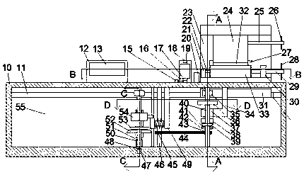
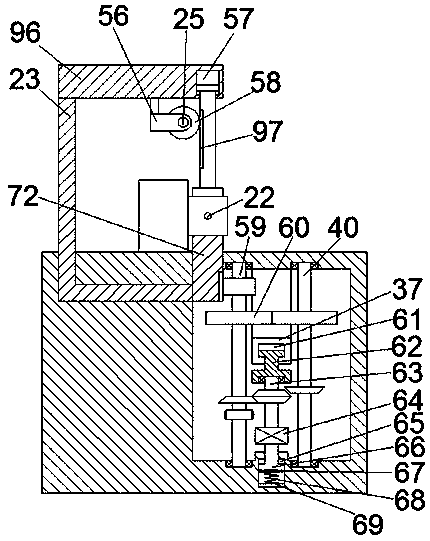
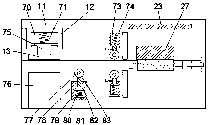
[0017] like Figure 1-5 As shown, a rack machining lathe of the device of the present invention includes a base 10, a transmission cavity 55 and a rail sliding cavity 11 are arranged in the base 10, and a start transmission device and a machining transmission are arranged in the transmission cavity 55. A clamping device and an electromagnet control block 94 located at the right end of the clamping device are slidably arranged in the rail sliding cavity 11, and a front-rear symmetrical milling cutter 20 and a ...


PUM


Abstract

The invention provides a rack machining lathe. The rack machining lathe comprises a base, wherein a transmission cavity and a track sliding cavity are arranged in the base, a starting transmission device and a machining transmission device are arranged in the transmission cavity, a clamping device and an electromagnet control block located at the right end of the clamping device are slidably arranged in the track sliding cavity, a milling cutter and a detection device which are symmetrical at front and back are fixedly mounted on the base, and the detection device comprises a detection slidingblock sliding frame and a displacement detection block fixedly mounted on the upper surface of the base. According to the racking machining lathe, a ratchet wheel is utilized to control the travel distances of to-be-machined racks, and the feeding of the to-be-machined racks is ensured to be the same when the racks are machined; and meanwhile, a milling device and a machining tooth device are mounted together, and the detection device is arranged in the middle, so that unqualified blank parts are repeatedly milled to be qualified by using the detection device while the manual carrying operation is reduced, and damage of the cutter caused by the fact that the flatness of to-be-machined rack surfaces and the back faces are unqualified is reduced.

Description

technical field [0001] The invention relates to the technical field of rack machining, in particular to a rack machining lathe. Background technique [0002] Rough machining of the rack is required before machining the teeth. After the initial machining is completed, the tooth surface to be machined and its back surface are milled flat, and the tooth surface to be machined and its back surface are milled flat to ensure the subsequent machining process. The teeth on the middle rack are qualified. If the to-be-machined tooth surface and its back surface of the workpiece are unqualified, the cutting edge of the tool is likely to be damaged or the entire tool is broken during the tooth machining process, and the travel distance of the rack during machining is not well controlled. After machining, The spacing between the individual teeth will be different, affecting the use of the rack. SUMMARY OF THE INVENTION [0003] In view of the deficiencies of the above technologies, t...

Claims


Application Information

Patent Timeline
Patent Type & Authority Applications(China)
IPC IPC(8): B23P23/02B23Q5/34
CPCB23P23/02B23Q5/34B23Q5/341
Inventor 不公告发明人
Owner PUJIANG SULI MASCH TECH CO LTD
Why Eureka
Try Eureka