
Vortex reactor and method of using same

A technology for reactors and reaction vessels, applied in chemical/physical/physicochemical stationary reactors, etc., can solve the problems of small effective reaction space, single flow form and fluid shear characteristics, and achieve extended residence time and structure Simple, easy to make and install

Pending Publication Date: 2020-05-08
南通海晴医药科技有限公司 +1
View PDF0 Cites 6 Cited by
  • Summary
  • Abstract
  • Description
  • Claims
  • Application Information

AI Technical Summary

Problems solved by technology

[0003] In order to solve the above problems, the present invention provides a vortex reactor and its use method to overcome the problems of small volume of effective reaction space and single flow form and fluid shear characteristics in the reactor

Method used


Image

  • Vortex reactor and method of using same
  • Vortex reactor and method of using same
  • Vortex reactor and method of using same

Examples


Embodiment 1

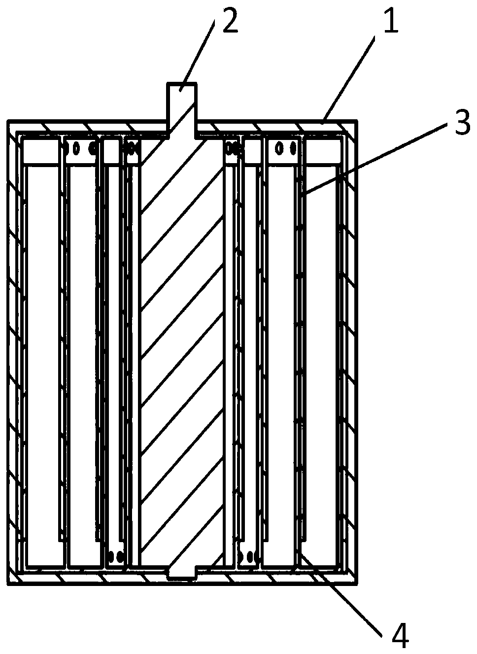
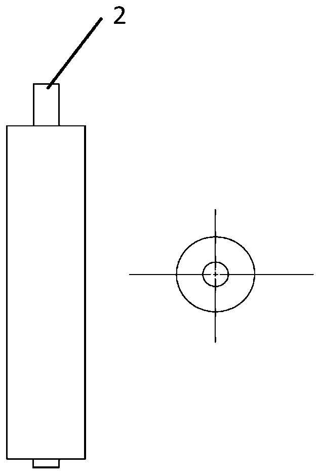
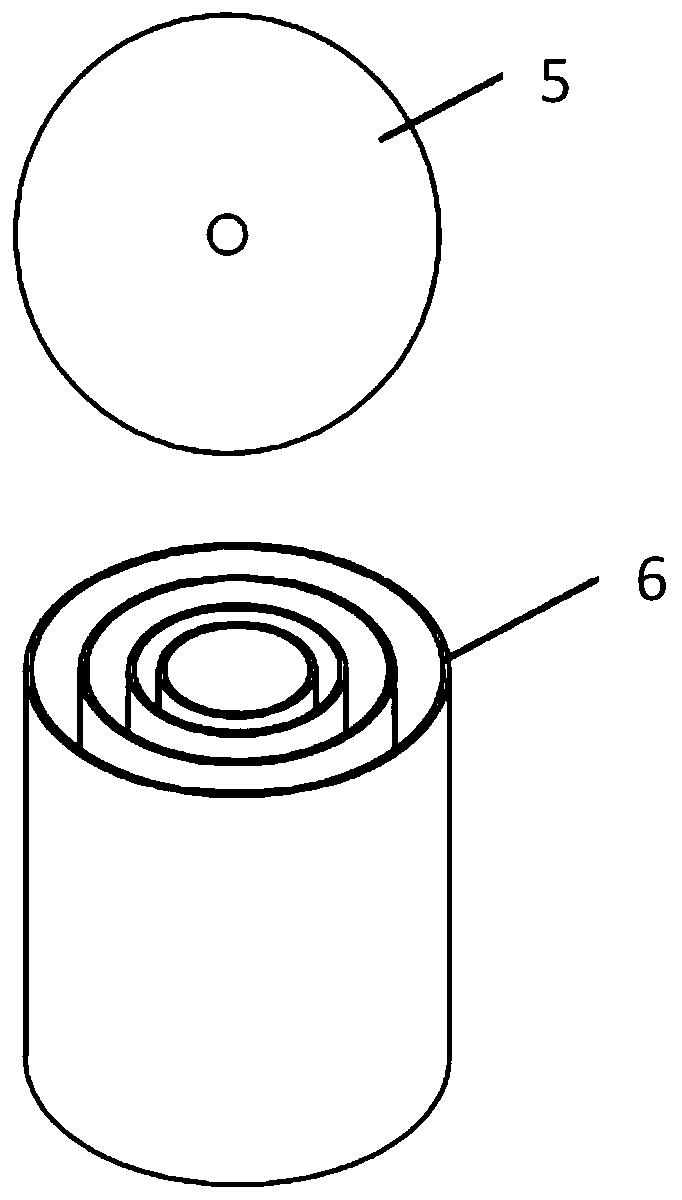
[0029] see figure 1 , a vortex reactor provided by an embodiment of the present invention, the reactor includes a reaction vessel 1, a rotating shaft 2, a rotor 3 and a stator 4, the reaction vessel 1 is a cylindrical structure, and the bottom is provided with a plurality of communicating external pipes inlet and outlet. A rotating shaft 2 is arranged at the center of the reaction vessel 1, such as figure 2 Shown is a schematic diagram of the connection relationship between the rotating shaft and the rotor according to an embodiment of the present invention. The rotor 3 is coaxially installed and fixedly connected to the rotating shaft 2. The rotating shaft 2 is driven to rotate by the motor. It is fixed on the bottom of the reaction vessel 1 and installed coaxially with the rotating shaft 2. The stator 4 and the rotor 3 are multi-layer nested cylindrical structures arranged coaxially at a certain radial distance, and the cylinders of each layer of the stator 4 are sleeved ...


PUM


Abstract

The invention provides a vortex reactor. The vortex reactor comprises a reaction container, a rotor and a stator, the rotor and the stator are arranged in the reaction container, the reaction container is cylindrical, the stator and the rotor are multilayer nested cylinders which are coaxially arranged according to a certain radial interval, and a plurality of independent and mutually communicatedannular spaces are formed between the stator and the rotor. According to the invention, the volume of the reactor can be fully utilized, the retention of materials is prolonged, and the shearing stress of the fluid in the annular space is controllably adjusted, so that the special requirements of reactants and products on flowing, shearing and mixing in different reaction stages are met, in addition, the mixing and suspension can be enhanced, and the application on an industrial scale is ensured.

Description

technical field [0001] The invention relates to the technical field of mechanical stirring reaction devices, in particular to a vortex reactor and a use method thereof. Background technique [0002] Mechanically stirred reactors are commonly used equipment in chemical production, mainly including containers, motor drives and stirring rotors, and the commonly used stirring rotors are impellers of various shapes. When the stirring rotor rotates, the materials in the container move under the drive of the stirring rotor to form vortices of various sizes to realize the transfer, mixing and reaction of substances. The structure of the reactor vessel and the stirring rotor is the key factor to control the flow pattern, velocity and direction of the material in the vessel, and the multi-scale vortex dynamic behavior, which directly affects the mixing, chemical reaction rate and conversion rate, and even the molecular structure. Common mechanically stirred reactors include impeller-...

Claims


Application Information

Patent Timeline
IPC IPC(8): B01J19/18
CPCB01J19/18
Inventor 李光
Owner 南通海晴医药科技有限公司
Learn More