
Bracket for sensor unit

一种传感器单元、发送器的技术,应用在仪器、电气元件、测量仪器组件等方向

Active Publication Date: 2022-05-03
ROBERT BOSCH GMBH
View PDF18 Cites 0 Cited by
  • Summary
  • Abstract
  • Description
  • Claims
  • Application Information

AI Technical Summary

Problems solved by technology

This enables the thermoplastic injection process to be optimized for specific applications

Method used


Image

  • Bracket for sensor unit
  • Bracket for sensor unit
  • Bracket for sensor unit

Examples


Embodiment Construction

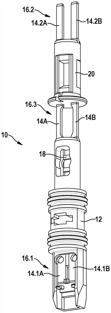
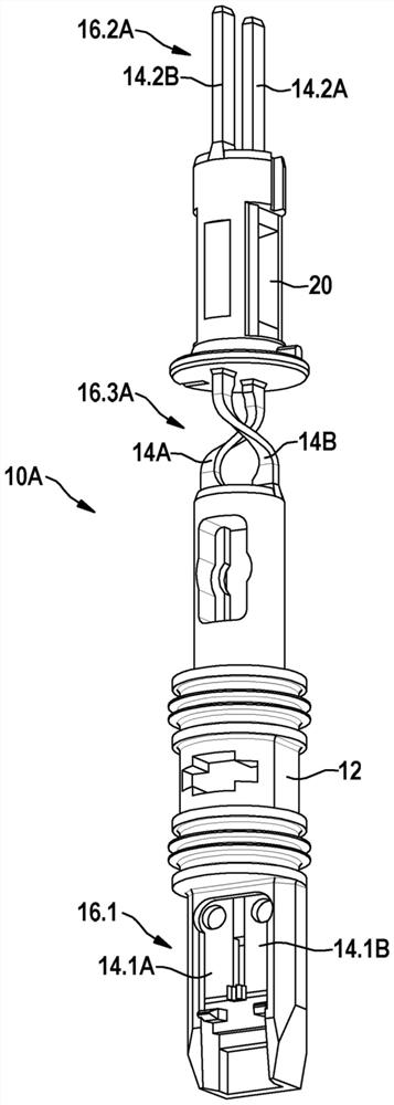
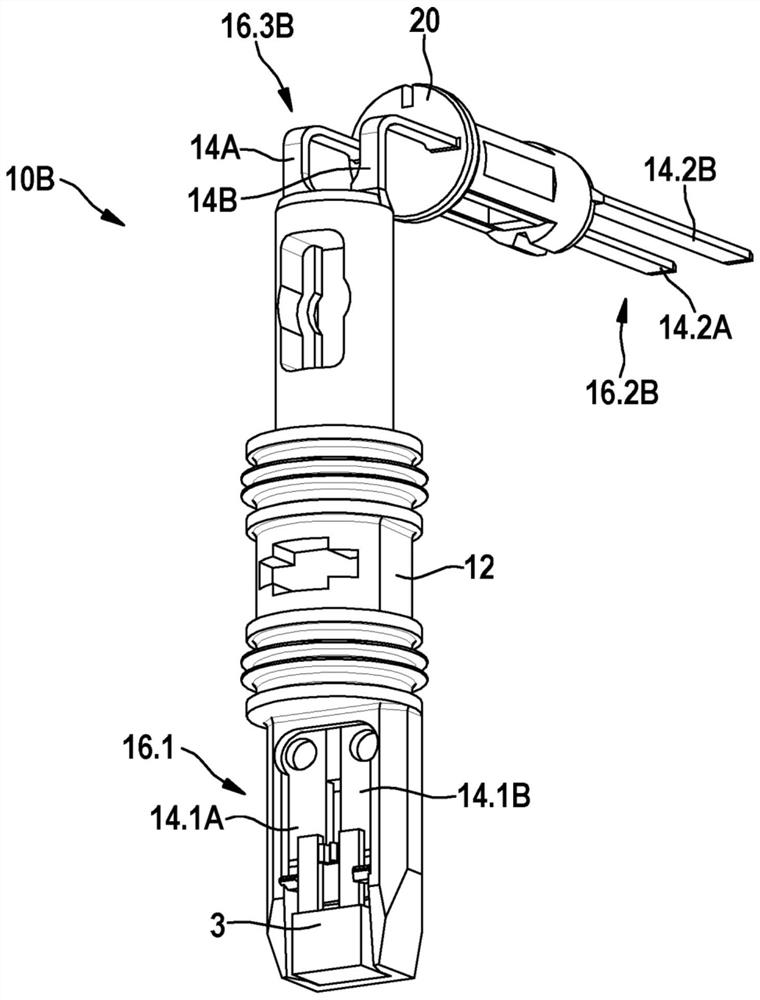
[0040] as by Figure 1 to Figure 7 It can be seen that the illustrated embodiment of the bracket 10 , 10A, 10B, 10C according to the invention for a sensor unit ( 1 ) comprises at least two bus bars 14A, 14B, respectively. The internal electrical interface 16 . 1 to the measured value transmitter 3 is formed at the first ends of at least two bus bars 14A, 14B. The external electrical connections 16.2, 16.2A, 16.2B, 16.2C for the plug module 5 are formed at the second ends of the at least two busbars 14A, 14B. Here, the orientation member 20 surrounds at least two bus bars 14A, 14B and is arranged between the internal electrical connection 16.1 and the external electrical connection 16.2, 16.2A, 16.2B, 16.2C. The orientation of the orientation member 20 determines the output direction of the second ends of the at least two bus bars 14A, 14B and the external electrical interface 16.2, 16.2A, 16.2B, 16.2C.

[0041] In the illustrated embodiment, the carrier 10 , 10A, 10B, 10C e...


PUM


Abstract

The invention relates to a bracket (10A) for a sensor unit, a vehicle sensor unit having such a bracket (10A), and a method of mounting such a sensor unit, wherein the bracket has at least two bus bars (14A, 14B), wherein The internal electrical interface (16.1) to the measured value transmitter is formed at the first ends of at least two bus bars (14A, 14B), and the external electrical interface (16.2A) for the plug module is formed at the at least two bus bars At the second end of the strip (14A, 14B). Here, the orientation member (20) surrounds at least two bus bars (14A, 14B) and is arranged between the internal electrical connection (16.1) and the external electrical connection (16.2A), wherein the orientation of the orientation member (20) determines at least The output direction of the second ends of the two bus bars (14A, 14B) and the external electrical interface (16.2A).

Description

technical field [0001] The invention relates to a carrier for a sensor unit, which has at least two one-piece bus bars, wherein an internal electrical connection to a measured value transmitter is formed at a first end of the at least two bus bars, and An external electrical connection for the plug module is formed at the second end of the at least two busbars. The subject matter of the present invention also includes a sensor unit for a vehicle having such a bracket and a mounting method of such a sensor unit. Background technique [0002] It is known that plug-in sensor units embodied as rotational speed sensors are constructed by electrical connection of a measured value transmitter at at least two bus bars, wherein the measured value transmitter comprises, for example, a sensor element and a sensor embodied as an application-specific integrated circuit (ASIC) circuit. In this case, the internal electrical connection to the measured value transmitter is formed at the fi...

Claims


Application Information

Patent Timeline
Patent Type & Authority Patents(China)
IPC IPC(8): G01D11/24
CPCG01D11/245H01R13/562H01R13/5845G01P1/02
Inventor R·施泰因布林克S·舒尔策A·黑加兹
Owner ROBERT BOSCH GMBH
Learn More