Power module and manufacturing method thereof

A technology for power modules and manufacturing methods, which is applied in electrical components, electrical solid state devices, circuits, etc., can solve problems such as high process costs and reduced market competitiveness.

Active Publication Date: 2020-05-05
DELTA ELECTRONICS SHANGHAI CO LTD
View PDF11 Cites 0 Cited by
  • Summary
  • Abstract
  • Description
  • Claims
  • Application Information

AI Technical Summary

Problems solved by technology

On the contrary, if the thickness of the metal layer is increased, the process cost will be higher, resulting in lower market competitiveness

Method used


Image

  • Power module and manufacturing method thereof
  • Power module and manufacturing method thereof
  • Power module and manufacturing method thereof

Examples


Embodiment Construction

[0100] Some typical embodiments embodying the features and advantages of the present disclosure will be described in detail in the description in the following paragraphs. It should be understood that the disclosure is capable of various changes in different embodiments without departing from the scope of the disclosure, and that the description and drawings therein are illustrative in nature and not limiting. This disclosure.

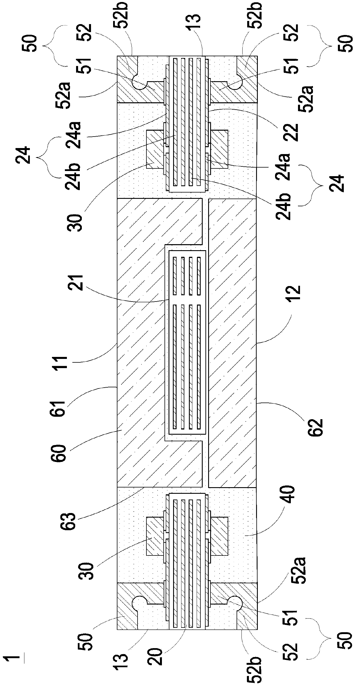
[0101] figure 1 is a schematic diagram of the cross-sectional structure of the power module disclosing the first preferred embodiment of the present disclosure. In this embodiment, the power module 1 includes a carrier board 20 , a power device 30 , a plastic package 40 and a lead assembly 50 . The carrier board 20 includes a first surface 21 and a second surface 22 , wherein the first surface 21 and the second surface 22 of the carrier board 20 are opposite to each other, and the carrier board 20 further includes a conducting circuit 24 . The carri...


PUM


Abstract

The invention relates to a power module and a manufacturing method thereof. The power module comprises a carrier plate, a power device, a pin assembly and at least one plastic package part. The carrier plate comprises a first surface and a second surface, wherein the first surface and the second surface are opposite to each other; and the carrier plate comprises a conducting circuit. The power device is arranged on the carrier plate, and the power device is electrically connected with the conducting circuit. The pin assembly is arranged on the carrier plate and comprises a first horizontal part and a vertical part which are connected, wherein the vertical part is electrically connected with the conducting circuit of the carrier plate. The pin assembly is provided with a first contact surface and a second contact surface, wherein the first contact surface and the second contact surface are not coplanar. The at least one plastic package part is arranged on the carrier plate, and at leastpartially covers the carrier plate and at least partially covers the pin assembly, and the first contact surface and the second contact surface of the pin assembly are exposed out of the plastic package part. The power module has a first surface and a first side surface, wherein the first contact surface is located on the first surface of the power module, and the second contact surface is located on the first side surface of the power module.

Description

technical field [0001] The present disclosure relates to a power module, in particular to a power module with an optimized pin assembly structure and a manufacturing method thereof. Background technique [0002] A traditional power module, such as a DC / DC converter, usually includes power devices, magnetic components, capacitors, a carrier board, and pin terminals. The carrier board is used to carry power devices and interconnect the carrier boards of power devices, capacitors and magnetic components. Wherein, the outlet terminal included in the existing power module is a wave pin, which has the advantage of large flow capacity, but occupies a large area. In addition, in order to ensure the convenience of the manufacturing process, the height of the wave pin should be less than twice its length or width, and at the same time, a certain minimum length or width must be guaranteed to be no less than 1mm. However, these conditions are not conducive to reducing the size of the ...

Claims


Application Information

Patent Timeline
IPC IPC(8): H01L23/31H01L23/492H01L23/48
CPCH01L23/3121H01L23/492H01L23/48
Inventor 洪守玉叶益青鲁凯陈庆东梁乐曾剑鸿
Owner DELTA ELECTRONICS SHANGHAI CO LTD
Why Eureka
Try Eureka