


Quick Research
Generate reliable direction feasibility study reports for your R&D in just a few steps.

Technical Q&A
Discover and master advanced knowledge NOW. Basics, ideas, possibilities, all at once.

Find Solutions
As an expert in R&D theories, this can generate solutions to your technical problems instantly.

Evaluate Feasibility
Analyze your overall solution with one click, know your potential R&D risks in advance.

Monitor Landscape
Get weekly tech updates, stay abreast of the latest tech innovations and key insights.
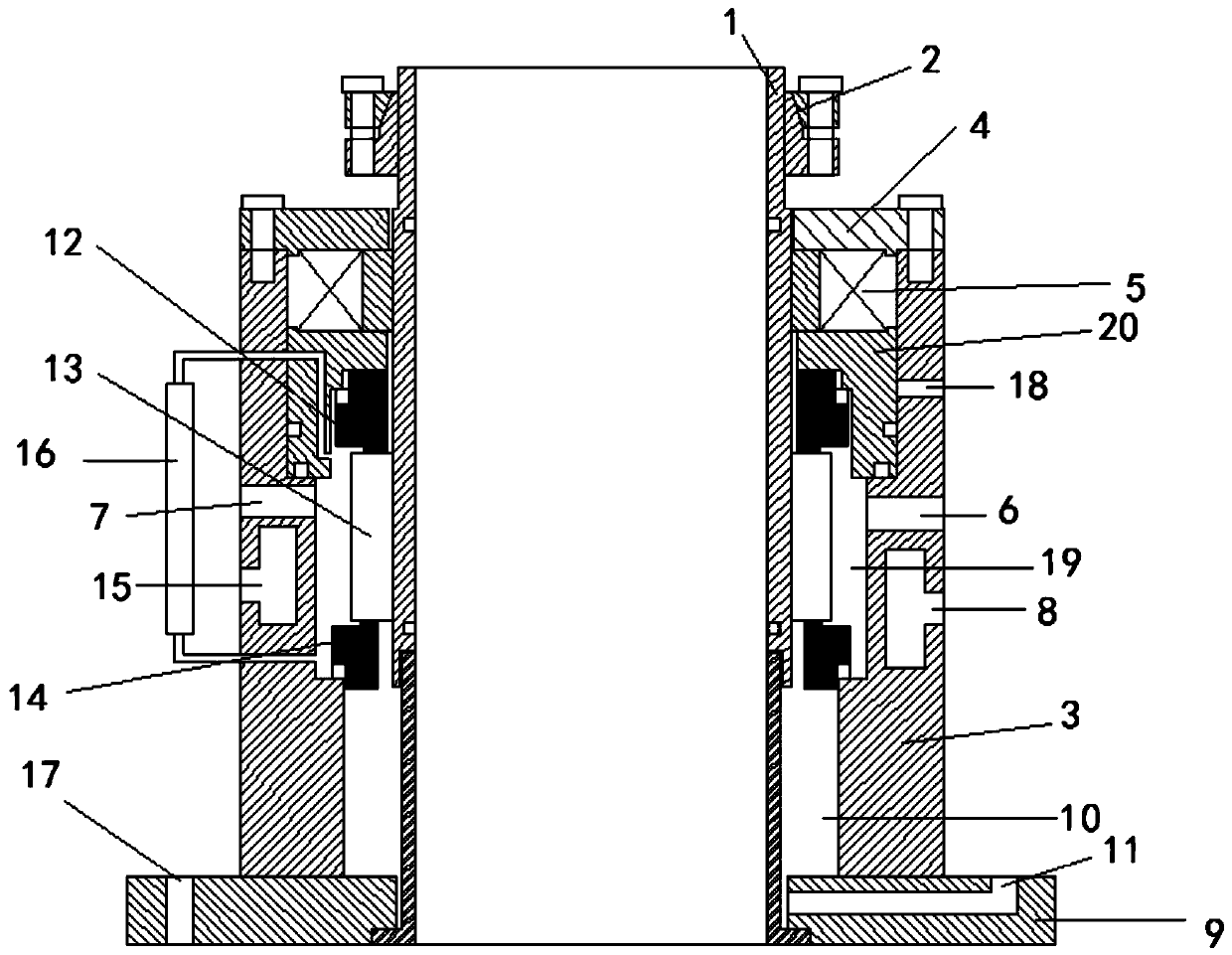
Dual-end-face mechanical seal
A mechanical seal and double-end technology, which is applied in the direction of engine seal, mechanical equipment, engine components, etc., can solve the problems of double-end mechanical seal damage, leakage of mechanical seal sealing fluid, large pressure difference of mechanical seal, etc., to ensure product quality safe effect
- Summary
- Abstract
- Description
- Claims
- Application Information
AI Technical Summary
Problems solved by technology
Method used
Image

Examples
Embodiment 1
[0023] like figure 1 A double-end mechanical seal, including a sealing box 3 arranged outside the shaft sleeve 1, the upper end of the sealing box 3 is movably connected with the shaft sleeve 1 through a sealed bearing 5, and the bottom of the sealing box 3 is fixedly connected with a lower The static ring seat 9, and the bottom of the bushing 1 is movably connected with the lower static ring seat 9; when in use, the lower static ring seat 9 is fixedly connected with the reaction kettle through the bolt holes arranged on the lower static ring seat 9, The bottom of the sealed box 3 is fixedly provided with a box cover 4, which can ensure the tightness of the whole sealed box, and the shaft sleeve 1 is movably connected with the sealed box 3 through the sealed bearing 5, so that the sealed box can be guaranteed to be sealed. The shaft sleeve can rotate relative to the sealing box;
[0024] The inner wall of the sealed box 3 below the sealed bearing 5 is provided with an annular...
PUM
 Abstract
Description
Claims
Application Information
 - R&D Engineer
- R&D Manager
- IP Professional
- Industry Leading Data Capabilities
- Powerful AI technology
- Patent DNA Extraction
Browse by: Latest US Patents, China's latest patents, Technical Efficacy Thesaurus, Application Domain, Technology Topic, Popular Technical Reports.
© 2024 PatSnap. All rights reserved.Legal|Privacy policy|Modern Slavery Act Transparency Statement|Sitemap|About US| Contact US: help@patsnap.com