
Automatic stamping equipment for accountancy

An automatic and equipment technology, applied in printing, object separation, stamping, etc., can solve problems such as reduced work efficiency and troublesome operation

Active Publication Date: 2020-05-01
陈曦
View PDF6 Cites 21 Cited by
  • Summary
  • Abstract
  • Description
  • Claims
  • Application Information

AI Technical Summary

Problems solved by technology

[0005] In order to overcome the need for people to continuously remove the stamped documents and then place new documents, such an operation is cumbersome and leads to a decrease in work efficiency. , no need for human operation, more convenient, and those with high work efficiency will remember to use automatic stamping equipment

Method used


Image

  • Automatic stamping equipment for accountancy
  • Automatic stamping equipment for accountancy
  • Automatic stamping equipment for accountancy

Examples


Embodiment 1

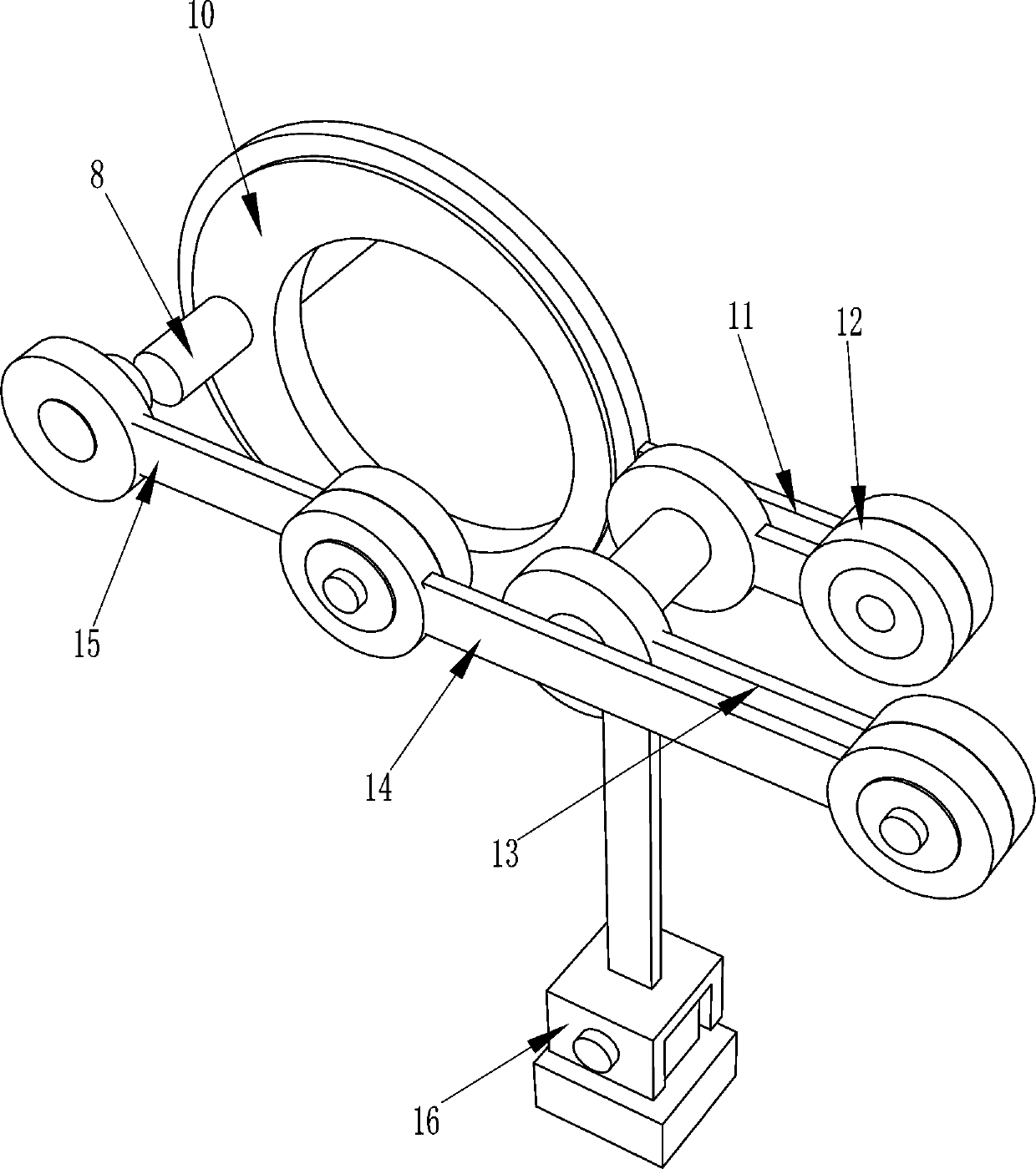
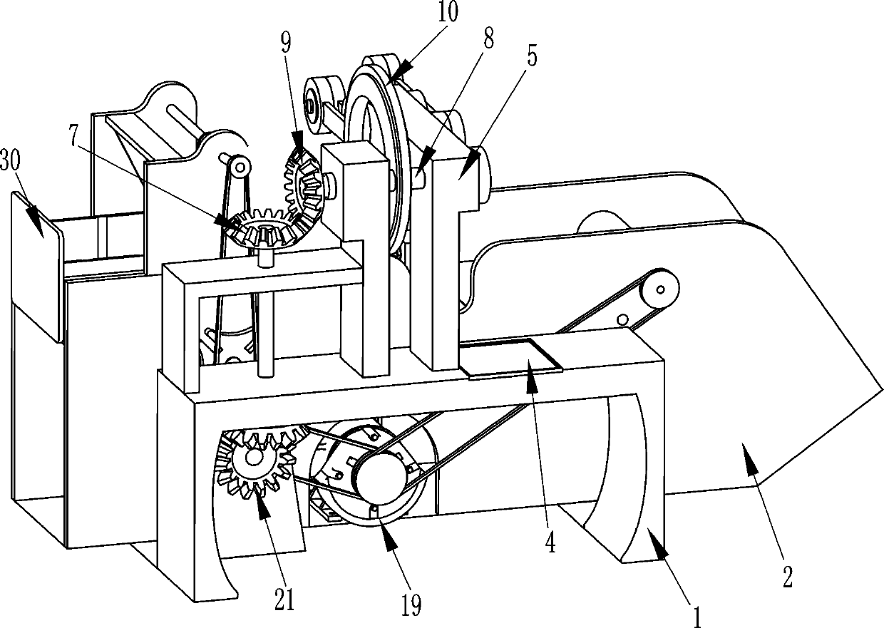
[0021] see Figure 1-Figure 4 , an automatic stamping device for recording, including a frame 1, a body 2, a collection box 3, an ink pad box 4, a stamping mechanism, a conveying mechanism, a pushing mechanism, a placement box 30, a friction plate 31 and a spring 32, the machine The body 2 is installed at the rear of the frame 1, the lower part of the right side of the body 2 is equipped with a collection box 3, the upper part of the left side of the body 2 is slidingly provided with a storage box 30, and the sliding type in the storage box 30 is provided with a friction plate 31, and the bottom of the friction plate 31 A spring 32 is connected to the inner bottom of the placement box 30, and a conveying mechanism is provided in the body 2, which is located on the right side of the placing box 30 to cooperate with it, and the conveying mechanism cooperates with the collection box 3, and the left side of the top of the body 2 is in contact with the conveying mechanism. A pushin...

Embodiment 2

[0030] see figure 2 and Figure 5 Compared with Embodiment 1, the main difference of this embodiment is that in this embodiment, a screw rod 17 and a nut 18 are also included, and a nut 18 is embedded in the middle part on the left side of the jacket 16, and the middle part on the right side of the jacket 16 is a rotating type. There is a screw mandrel 17 that can fix the seal, and the screw mandrel 17 cooperates with the nut 18.

[0031] It also includes auxiliary wheels 28 and a second transmission device 29. An auxiliary wheel 28 is rotatably connected between the upper right side of the body 2. The auxiliary wheel 28 cooperates with the conveyor belt 27. The auxiliary wheel 28 and the transmission part 24 are connected with a second transmission. Two transmissions 29.

[0032] When the seal is stuck in the jacket 16, you can twist the screw mandrel 17 to rotate forward, the screw mandrel 17 is turning to the left and move to the left, the screw mandrel 17 moves to the l...


PUM


Abstract

The invention relates to stamping equipment, in particular to automatic stamping equipment for accountancy. The purpose that the automatic stamping equipment for the accountancy can always conduct conveying stamping on files, does not need to be operated by people, and is convenient to operate and high in working efficiency is achieved. The automatic stamping equipment for the accountancy comprises a rack, a machine body is installed on one side of the rack, a containing box is slidably arranged on one side of the machine body, springs are connected to the inner side of the containing box, a friction plate is slidably arranged in the containing box, one side of the friction plate is fixedly connected with the tail ends of the springs, and a collecting box is installed on the side, far awayfrom the containing box, of the interior of the machine body. According to the automatic stamping equipment for the accountancy, the files are put into the containing box to make contact with a pickup roller, a motor is started to reversely rotate, then the pickup roller can drive the files to move to a conveyer belt, the conveyer belt rotates forwards to drive the files to move rightwards, a clamping sleeve drives a stamp to stamp the files, therefore, the working efficiency is high, operation is convenient, and manual operation is not needed.

Description

technical field [0001] The invention relates to a stamping device, in particular to an automatic stamping device for recording. Background technique [0002] Accounting has two meanings, one refers to accounting work, and the other refers to accounting staff. Accounting work is to check accounting vouchers, financial account books, and financial statements in accordance with the "Accounting Law", "Budget Law", and "Statistics Law", and engage in economic work. The process of accounting and supervision is a kind of economic management work that uses currency as the main unit of measurement and uses special methods to calculate and supervise the economic activities of a unit; accounting staff is the person who performs accounting work. Accounting, property management, cashiers and other personnel, when the accountant is working, there are a large number of documents that need to be stamped, so they need to use the seal. [0003] Existing automatic sealing device, as the Chine...

Claims


Application Information

Patent Timeline
Patent Type & Authority Applications(China)
IPC IPC(8): B41K3/04B65H3/06
CPCB41K3/04B65H3/06B65H2701/1131
Inventor 不公告发明人
Owner 陈曦
Learn More