
Automatic feeding device for valve seat ring

A technology of automatic feeding and valve seat ring, applied in the directions of transportation and packaging, conveyors, conveyor objects, etc., can solve the problems of low feeding efficiency, high jam rate, complex structure, etc., to reduce the jam rate and simple structure. , the effect of reducing costs

Inactive Publication Date: 2020-04-28
SAIC-GM-WULING AUTOMOBILE CO LTD
View PDF5 Cites 1 Cited by
  • Summary
  • Abstract
  • Description
  • Claims
  • Application Information

AI Technical Summary

Problems solved by technology

[0003] The object of the present invention is to provide an automatic valve seat feeding device, aiming to solve the problems of the existing valve seat feeding device, which have complex structure, high material jam rate, low feeding efficiency and high cost

Method used


Image

  • Automatic feeding device for valve seat ring
  • Automatic feeding device for valve seat ring
  • Automatic feeding device for valve seat ring

Examples


Embodiment Construction

[0021] Specific embodiments of the present invention are described with reference to the above drawings.

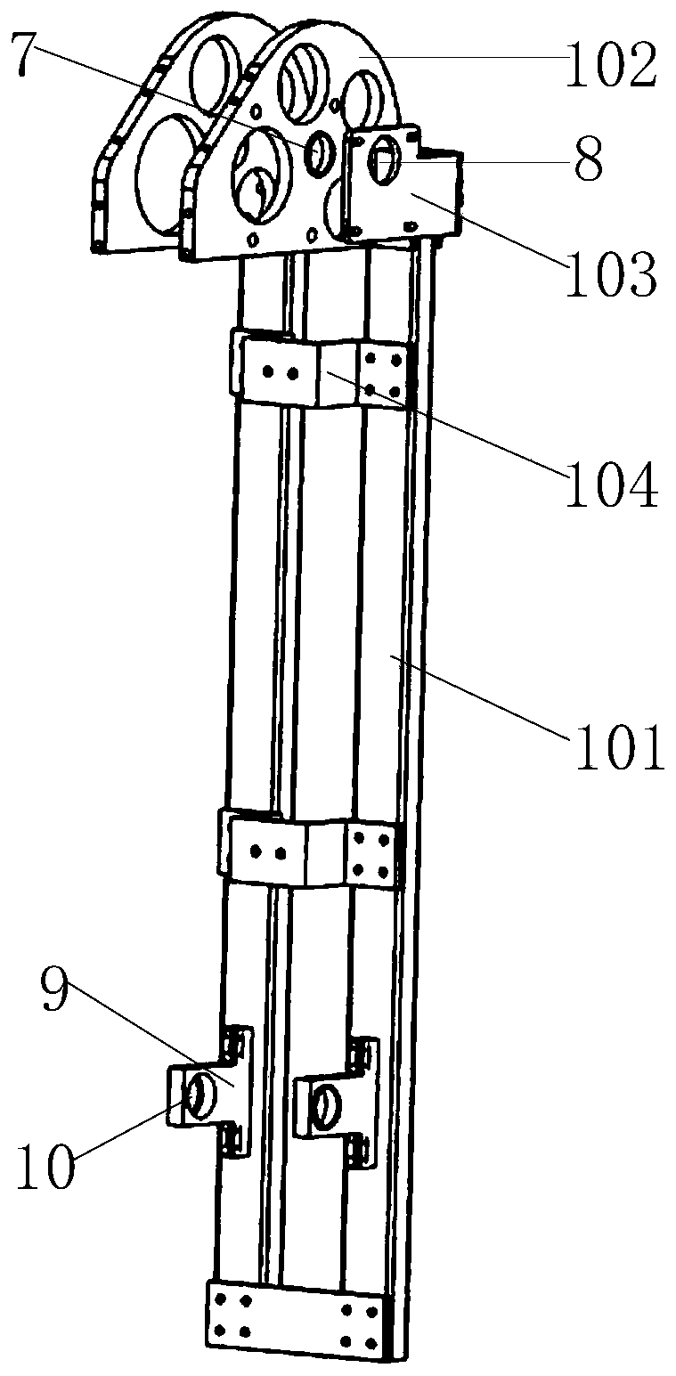
[0022] like Figure 1-5 As shown, a valve seat automatic feeding device in this embodiment includes a support mechanism 1, a transmission mechanism 2 is provided on one side of the support mechanism 1, a drive mechanism 3 for driving the transmission mechanism 2 and a setting In the actuator 4 on the transmission mechanism 2, the other side of the support mechanism 1 is provided with a material storage box 5, and a gap 6 is provided on the side of the storage box 5 and close to the support mechanism 1, so that The actuator 4 includes a bottom plate 41 arranged on the transmission mechanism 2 and a material hook 42 connected to the bottom plate 41 . That is to say, in this embodiment, the actuator 4 has multiple groups, and the angle formed between the material hook 42 and the bottom plate 41 is 60°, which is convenient for hooking the seat ring; the material hook 42 It ...


PUM


Abstract

The invention is applicable to the technical field of valve seat ring machining, and provides an automatic feeding device for a valve seat ring. The automatic feeding device for the valve seat ring comprises a supporting mechanism, wherein one side of the supporting mechanism is provided with a transmission mechanism, a driving mechanism used for driving the transmission mechanism and an executingmechanism arranged on the transmission mechanism, the other side of the supporting mechanism is provided with a material containing box, one side, close to the supporting mechanism, of the material containing box is provided with a gap, and the executing mechanism comprises a bottom plate arranged on the transmission mechanism and a material hook connected with the bottom plate. According to theautomatic feeding device for the valve seat ring, the driving mechanism drives the transmission mechanism to further drive the executing mechanism on the transmission mechanism to operate, the material hook on the executing mechanism passes through the gap of the material containing box and hooks the valve seat ring in the material containing box to achieve the effect of feeding, the device is simple in structure, the cost is reduced, the material clamping rate is reduced, and the feeding efficiency is improved.

Description

technical field [0001] The invention belongs to the technical field of valve seat ring processing, in particular to an automatic valve seat feeding device. Background technique [0002] At present, the automatic feeding devices for valve seat rings existing at home and abroad adopt the ring-shaped vibrating material tray feeding method, and use the ring-shaped vibrating material plate to sort the disordered valve seat rings and vibrate them to the material channel. The entire device includes a ring vibrating device, a material tray, a linear material channel, a support system, etc., and the structure is very complicated and expensive; the vibration mode of the vibrating material plate has a high rate of material jamming, and frequent vibrator failures; frequent vibrations and slow advance speed of the seat ring , high energy consumption and low efficiency. Contents of the invention [0003] The object of the present invention is to provide an automatic valve seat feeding ...

Claims


Application Information

Patent Timeline
IPC IPC(8): B65G47/40B65G17/12
CPCB65G17/126B65G47/40
Inventor 曾宪献蒋烁烁王伟许可会李建敏
Owner SAIC-GM-WULING AUTOMOBILE CO LTD
Learn More