Laser hole making method for carbon fiber composite material and tooling fixture thereof

A technology of composite materials and fixtures, which is applied in the direction of manufacturing tools, laser welding equipment, metal processing equipment, etc., can solve problems such as thermal defects, and achieve the effects of improved precision, low processing cost, and neat edges

Pending Publication Date: 2020-04-28
SHANGHAI INST OF LASER TECH
View PDF0 Cites 5 Cited by
  • Summary
  • Abstract
  • Description
  • Claims
  • Application Information

AI Technical Summary

Problems solved by technology

[0005] The technical problem to be solved by the present invention is to overcome the thermal defects caused by laser processing in the prior art, and provide a processing method that can improve the quality of laser hole making of carbon fiber composite materials

Method used


Image

  • Laser hole making method for carbon fiber composite material and tooling fixture thereof
  • Laser hole making method for carbon fiber composite material and tooling fixture thereof
  • Laser hole making method for carbon fiber composite material and tooling fixture thereof

Examples


Embodiment 1

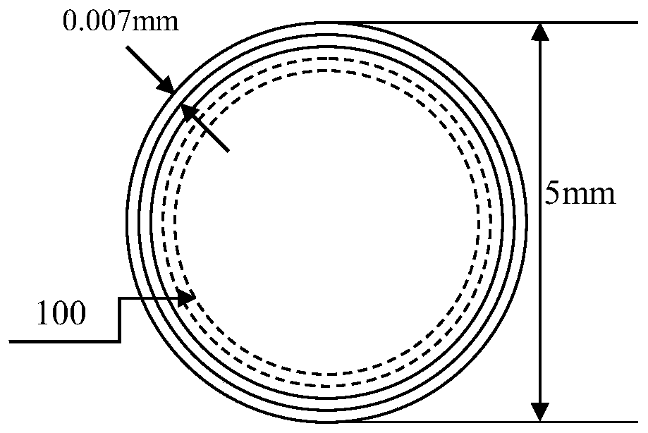
[0040] The circular ring adopts such as Figure 2a The concentric circles shown are scanned in circles from outside to inside, refer to Figure 3a , the edges of the concentric holes made in this way are relatively neat, the surface morphology is good, and there is a small amount of heat-affected zone. Refer to Figure 4a It can be seen that the concentric circular holes have a heat-affected zone of about 110 μm. Figure 5c The inner wall roughness Sa of the middle mechanical hole is 4.02μm, the reference Figure 5a , The roughness Sa of the inner wall of the concentric circle hole is only 3.01 μm, and the roughness is significantly reduced.

Embodiment 2

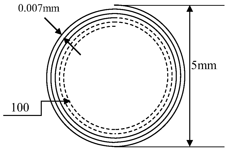
[0042] Different from Example 1, the circular ring adopts such as Figure 2b The spiral circle shown is scanned from the outside to the inside, refer to Figure 3b , the edge of the hole of the spiral circle hole made in this way is more tidy in Example 1, the surface morphology is good, and there is a small amount of heat-affected zone. Refer to Figure 4b It can be seen that the heat-affected zone of the spiral circular hole is further reduced compared with Example 1, and the heat-affected zone of the spiral circular hole is about 75 μm. Figure 5c The inner wall roughness Sa of the middle mechanical hole is 4.02μm, the reference Figure 5b , the roughness Sa of the inner wall of the spiral circle hole is only 2.61 μm, and the roughness is significantly reduced.

[0043] In the above two examples, KEYENCE optical microscopes were used to observe the surface morphology of the laser-made holes, the morphology of the inner wall of the hole, and measure the roughness of the in...


PUM

PropertyMeasurementUnit
diameteraaaaaaaaaa
surface roughnessaaaaaaaaaa

Abstract

The invention discloses a laser hole making method for a carbon fiber composite material. The method comprises the following steps that 1, surface wiping is performed on the carbon fiber composite material to be treated with alcohol cotton, surface pollutants are removed, the carbon fiber composite material is aired and then the carbon fiber composite material is used for later use; and 2, the carbon fiber composite material obtained in the step 1 is subjected to laser scanning machining treatment according to a designed scanning track by adopting an ultrashort pulse laser machining system, and machining holes with different apertures are prepared; and an ultrashort pulse laser adopts a picosecond laser, so that the defects such as thermal effect caused by long pulse laser machining can beavoided. The hole surfaces prepared by the laser hole making method is good in morphology, neat in edge and free of obvious defects, and compared with a mechanical hole making mode, the heat radiation area can be remarkably reduced, the roughness of the inner walls of the round holes is reduced, and the hole making precision is improved. The invention further discloses a tooling fixture suitablefor the laser hole making method of the carbon fiber composite material, the tooling fixture suitable for the laser hole making method of the carbon fiber composite material can effectively reduce thetemperature of the machining area and can reduce the heat radiation area.

Description

technical field [0001] The invention relates to a laser hole-making method of a carbon fiber composite material and a fixture, belonging to the technical field of laser processing of carbon fiber composite materials. Background technique [0002] Carbon Fiber Reinforced Plastic (CFRP for short) has the advantages of high specific strength, high specific stiffness, low density, stable structure and size, strong designability, good fatigue resistance and corrosion resistance, etc., which are all other traditional materials. Due to its incomparable and alternative superior properties, it is widely used in aviation, automobile, rail transit and other fields. [0003] After CFRP is formed, in most cases, a large number of hole-making processes are required to meet the requirements of assembly and connection. The processing quality of connection holes is directly related to the assembly quality and service life of parts. CFRP is a two-phase or multi-phase structure composed of ca...

Claims


Application Information

Patent Timeline
Patent Type & Authority Applications(China)
IPC IPC(8): B23K26/382B23K26/402B23K26/02B23K26/142
CPCB23K26/382B23K26/402B23K26/142B23K26/02
Inventor 张瑄珺王健超董岿然沈佳骏汪于涛王嘉齐吴鸯
Owner SHANGHAI INST OF LASER TECH
Why Eureka
Try Eureka