Centrifugal dehumidifying and spin-drying machine

A centrifugal, drying machine technology, applied in dryers, drying, drying of solid materials, etc., can solve the problems of low drying efficiency and high energy consumption of the drying machine, and achieve simple structure, low noise, high energy consumption, etc. Efficient drying effect

Pending Publication Date: 2020-04-24
瓷金科技(河南)有限公司
View PDF5 Cites 4 Cited by
  • Summary
  • Abstract
  • Description
  • Claims
  • Application Information

AI Technical Summary

Problems solved by technology

[0005] The purpose of the present invention is to provide a centrifugal drying machine to solve the technical problems of low drying efficiency and high energy consumption in the prior art

Method used


Image

  • Centrifugal dehumidifying and spin-drying machine
  • Centrifugal dehumidifying and spin-drying machine
  • Centrifugal dehumidifying and spin-drying machine

Examples


Embodiment Construction

[0026] In order to make the object, technical solution and advantages of the present invention clearer, the present invention will be further described in detail below in conjunction with the accompanying drawings and embodiments. It should be understood that the specific embodiments described here are only used to explain the present invention, and are not intended to limit the present invention, that is, the described embodiments are only some of the embodiments of the present invention, but not all of the embodiments. The components of the embodiments of the invention generally described and illustrated in the figures herein may be arranged and designed in a variety of different configurations.

[0027] Accordingly, the following detailed description of the embodiments of the invention provided in the accompanying drawings is not intended to limit the scope of the claimed invention, but merely represents selected embodiments of the invention. Based on the embodiments of the...


PUM


Abstract

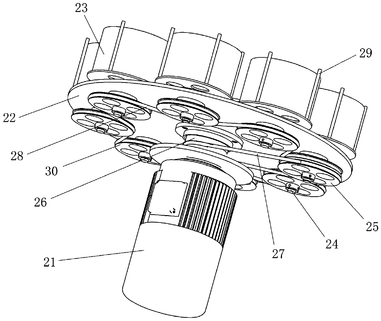
The invention relates to a centrifugal dehumidifying and spin-drying machine. The machine comprises a driving motor; a bearing piece is in transmission connection with the driving motor and can rotatearound a rotor rotating shaft of the driving motor under the driving of the driving motor; a plurality of charging barrels are provided for containing products to be spin-dried; each charging barrelcomprises a driving charging barrel and a driven charging barrel which are rotatably mounted on the bearing piece, the rotating axis of the charging barrels is parallel to the rotor rotating shaft ofthe driving motor, and all the charging barrels revolve around the rotor rotating shaft of the driving motor along with the bearing part to throw out liquid on a product; the centrifugal dehumidifyingand spin-drying machine further comprises a fixed wheel, the fixed wheel is relatively fixed to a shell of the driving motor, and the axis is coaxial with the rotor rotating shaft of the driving motor; and the driving charging barrel and the fixed wheel are in transmission through a driving annular transmission part, and the driving charging barrel can rotate under the driving of the annular transmission part during revolution; and the driven charging barrel is in transmission connection with the driving charging barrel. The spin-drying machine can realize high-efficiency spin-drying of products.

Description

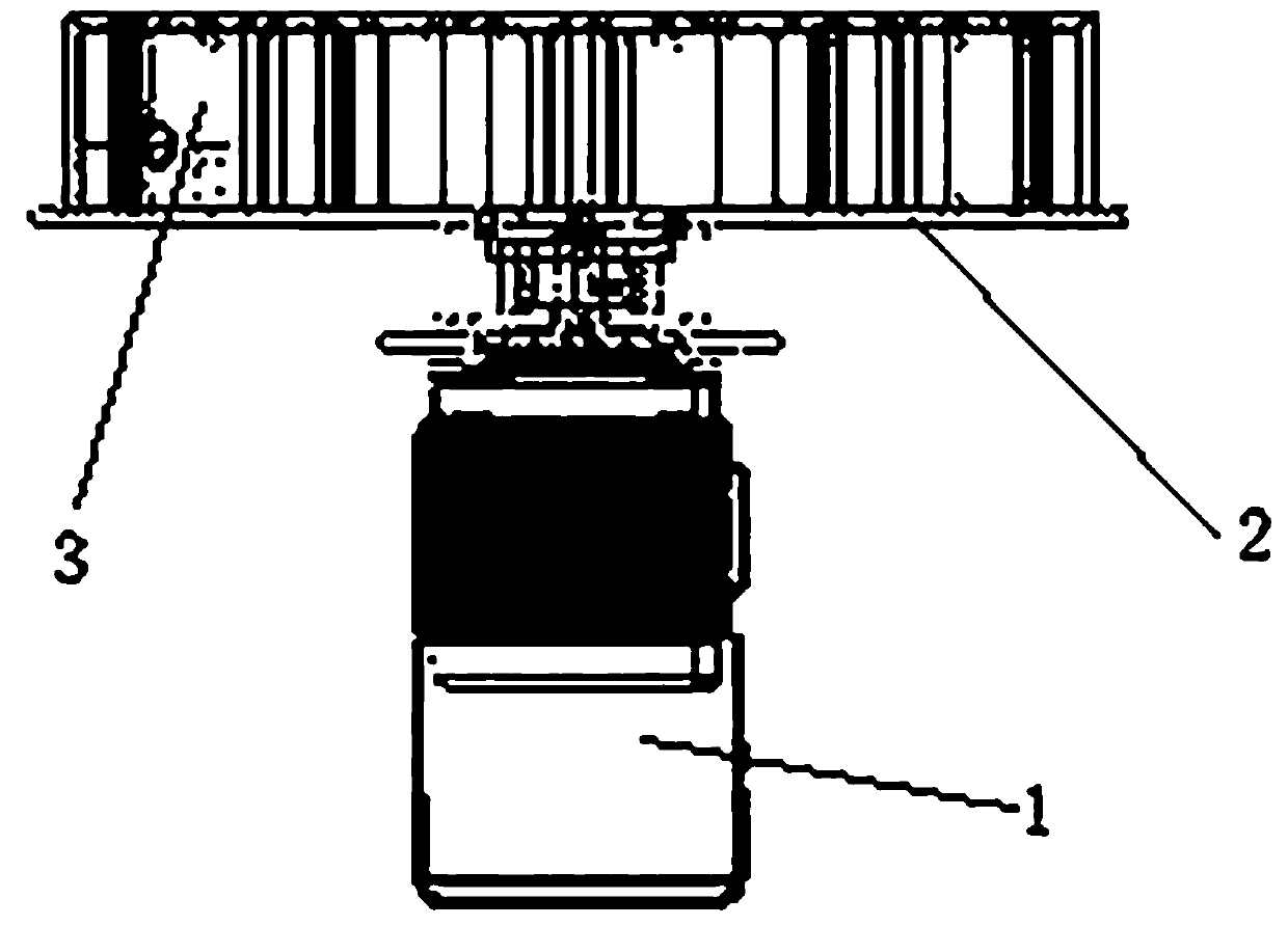
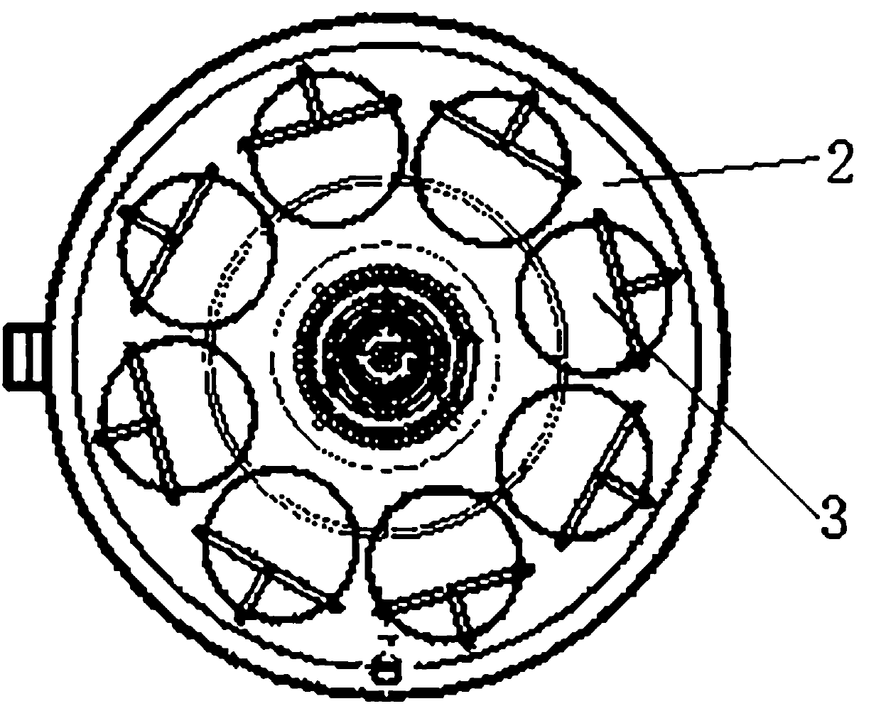
technical field [0001] The invention relates to a centrifugal type dehumidification and drying machine. Background technique [0002] In actual production, liquid will adhere to the products produced under some working conditions. For example, in order to improve the machining accuracy and reduce the wear of the tool and grinding wheel during machining, coolant will be sprayed on the tool head and grinding wheel, resulting in the adhesion of the processed product. There is cooling liquid; then there is the pickling treatment of the workpiece. In the last step of pickling treatment, tap water is used to clean the workpiece to clean the reaction liquid on the workpiece, which also causes liquid to adhere to the produced product. [0003] Products with liquid attached are inconvenient to be directly used or packaged in the next step. Therefore, in the actual operation process, corresponding dehumidification devices are often used to dry the wet products. Such as figure 1 and ...

Claims


Application Information

Patent Timeline
IPC IPC(8): F26B5/08F26B25/00F26B25/02F26B25/16
CPCF26B5/08F26B25/00F26B25/02F26B25/16
Inventor 刘永良王维李磊武志慧
Owner 瓷金科技(河南)有限公司
Why Eureka
Try Eureka