Garbage incinerator
A technology for waste incinerators and exhaust grilles, which is applied to incinerators, combustion methods, combustion types, etc., can solve the problem of only supplying gas from the center of the furnace, reduce gas consumption, prevent the generation of harmful gases, and set up area small effect
- Summary
- Abstract
- Description
- Claims
- Application Information
AI Technical Summary
Problems solved by technology
Method used
Image
Examples
no. 1 example
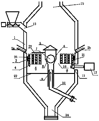
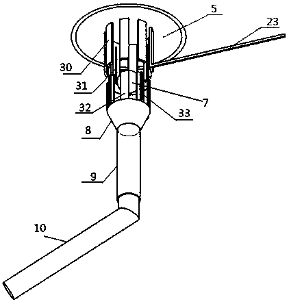
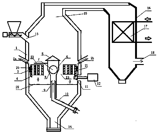
[0026] figure 1 It is a schematic diagram of the composition of the garbage incinerator provided by the first embodiment of the present invention, figure 2 It is a three-dimensional structural schematic diagram of some components of the gas supply device for a waste incinerator provided in the first embodiment of the present invention, as shown in Figure 1-2 As shown, the garbage incinerator provided by the present invention includes a shell 1 and a gas supply device, and also includes a rotary bed 3 arranged inside the furnace shell 1. The center of the rotary hearth 3 is provided with a through hole 19 along the axial direction, and the rotary hearth 3 A plurality of ash leakage holes are radially arranged on the periphery deviated from the center in the axial direction, and the rotation center axis of the rotary hearth 3 is arranged in the vertical direction, and rotates around the gas supply device in the horizontal plane. The air supply device includes an exhaust grid ...
no. 2 example
[0041] Figure 4 It is a schematic diagram of the composition of the garbage incinerator provided by the second embodiment of the present invention, such as Figure 4 As shown, the structure of the garbage incinerator provided by the second embodiment of the present invention is basically the same as that of the garbage incinerator provided by the first embodiment of the present invention. The filtering mechanism includes a partition 25 which is perpendicular to the axis of the casing and tightly combined with the inner wall of the casing. A smoke through hole 25 is arranged in the center of the partition 25 in the axial direction, and a smoke exhaust cap 26 is arranged on the through hole 25 . Because the present invention is equipped with a filter mechanism, the dust rolled up due to the swirling flow formed by the air supply device in the incineration chamber falls back into the incineration chamber, so that the inner chamber of the waste heat boiler and the heat exchanger ...
no. 3 example
[0043] Figure 5 It is a schematic diagram of the composition of the garbage incinerator provided by the fourth embodiment of the present invention, such as Figure 5 As shown, the structure of the garbage incinerator provided by the third embodiment of the present invention is basically the same as that of the garbage incinerator provided by the second embodiment of the present invention, the only difference is that the garbage incinerator also includes a motor 29, and the output of the motor 29 The shaft is connected to the conical wheel 28 through a reduction mechanism; an annular conical ring 27 is arranged along the circumference of the incinerator shell, and a plurality of gas supply pipes, such as 2a and gas supply pipe 2b, are fixed on the annular conical ring 27 by a fixing mechanism. The wheel 28 meshes with the conical gear ring 27. When the motor 29 works, the angle between the air supply pipe 2a, the air supply pipe 2b and the tangential direction of the inner cha...
PUM
 Abstract
Description
Claims
Application Information
 - R&D Engineer
- R&D Manager
- IP Professional
- Industry Leading Data Capabilities
- Powerful AI technology
- Patent DNA Extraction
Browse by: Latest US Patents, China's latest patents, Technical Efficacy Thesaurus, Application Domain, Technology Topic, Popular Technical Reports.
© 2024 PatSnap. All rights reserved.Legal|Privacy policy|Modern Slavery Act Transparency Statement|Sitemap|About US| Contact US: help@patsnap.com


