


Quick Research
Generate reliable direction feasibility study reports for your R&D in just a few steps.

Technical Q&A
Discover and master advanced knowledge NOW. Basics, ideas, possibilities, all at once.

Find Solutions
As an expert in R&D theories, this can generate solutions to your technical problems instantly.

Evaluate Feasibility
Analyze your overall solution with one click, know your potential R&D risks in advance.

Monitor Landscape
Get weekly tech updates, stay abreast of the latest tech innovations and key insights.
High-voltage cable channel steel cover plate turnover mechanism and method thereof
A technology of high-voltage cables and flap mechanism, which is applied to the installation of cables, cable installation devices, electrical components, etc., which can solve problems affecting the service life of cables, avoid yield problems and ensure stability
- Summary
- Abstract
- Description
- Claims
- Application Information
AI Technical Summary
Problems solved by technology
Method used
Image

Examples
Embodiment 1
[0043] First of all, it needs to be explained that the usage environment of this embodiment is a wharf.
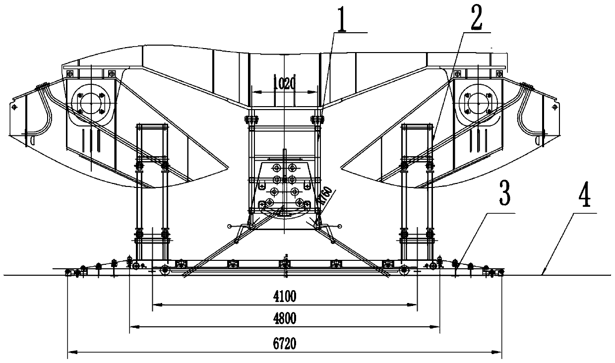
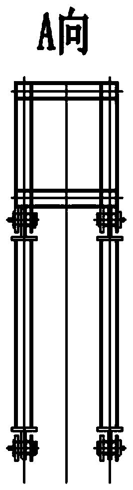
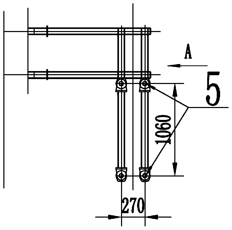
[0044] Please refer to figure 1 , Embodiment 1 discloses a high-voltage cable trough 4 steel cover flap mechanism, including a flap guide frame 3, a flap guide connecting bracket 2 and a cable guide frame, the flap guide frame 3 connects the bracket flap guide frame 3 It is connected with the complete machine trolley to provide power for the flap guide frame 3; the flap guide frame 3 is composed of five parts: the first frame body, the walking wheel, the guide wheel, and the support wheel, and the travel wheel, the guide wheel, and the support wheel are all connected to the The first frame body, in which the walking wheels and the guide frame 3 for ensuring the flap run smoothly on the upper part of the cable trough 4, the guide wheels and the supporting wheels ensure the normal opening and opening of the dock cover plate, and the unobstructed entry of cables into the slot...
Embodiment 2
[0062] Embodiment 2 discloses a method for using the high-voltage cable trough 4 steel cover flap mechanism disclosed in Embodiment 1, including the following steps:
[0063] The whole locomotive is started, and the whole locomotive provides power to the flap guide frame 3 through the flap guide connecting bracket 2, so that the flap guide frame 3 can move back and forth;
[0064] With the movement of the flap guide frame 3, the guide wheels support the stiffened plate under the cover plate, and open the steel cover plate from the horizontal state to the maximum open state;
[0065] The support wheel supports the main board on the cover, and the support wheel keeps the cover open, and the cable enters the cable channel at this time; the guide wheel on the other side supports the steel plate, puts down the steel cover, and completes the state transition of opening and closing.
PUM
 Abstract
Description
Claims
Application Information
 - R&D Engineer
- R&D Manager
- IP Professional
- Industry Leading Data Capabilities
- Powerful AI technology
- Patent DNA Extraction
Browse by: Latest US Patents, China's latest patents, Technical Efficacy Thesaurus, Application Domain, Technology Topic, Popular Technical Reports.
© 2024 PatSnap. All rights reserved.Legal|Privacy policy|Modern Slavery Act Transparency Statement|Sitemap|About US| Contact US: help@patsnap.com