
Display panel and display device

A technology for display panels and substrates, which is used in static indicators, instruments, organic semiconductor devices, etc., and can solve the problems that the border of the display panel cannot be further narrowed, and it is difficult to achieve no border.

Active Publication Date: 2022-06-03
SHANGHAI TIANMA MICRO ELECTRONICS CO LTD
View PDF7 Cites 0 Cited by
  • Summary
  • Abstract
  • Description
  • Claims
  • Application Information

AI Technical Summary

Problems solved by technology

The display panel in the prior art is usually provided with a frame area and a display area, and the frame area of ​​the display panel usually needs to be equipped with components such as driver chips or other peripheral components. The existence of these components makes the frame of the display panel unable to be further narrowed, making it more difficult to Achieve a borderless design

Method used


Image

  • Display panel and display device
  • Display panel and display device
  • Display panel and display device

Examples


Embodiment Construction

[0033] Various exemplary embodiments of the present invention will now be described in detail with reference to the accompanying drawings. It should be noted that the relative arrangement of the components and steps, the numerical expressions and numerical values ​​set forth in these embodiments do not limit the scope of the invention unless specifically stated otherwise.

[0034] The following description of at least one exemplary embodiment is merely illustrative in nature and is in no way intended to limit the invention, its application, or uses.

[0035] Techniques, methods, and apparatus known to those of ordinary skill in the relevant art may not be discussed in detail, but where appropriate, such techniques, methods, and apparatus should be considered part of the specification.

[0036] In all examples shown and discussed herein, any specific values ​​should be construed as illustrative only and not limiting. Accordingly, other instances of the exemplary embodiment may...


PUM


Abstract

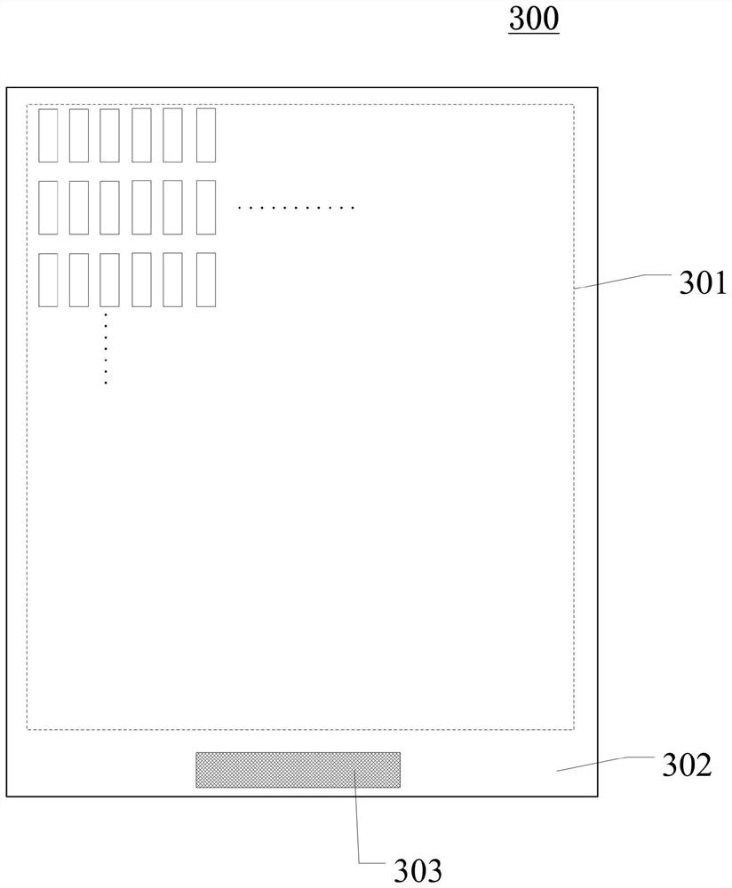
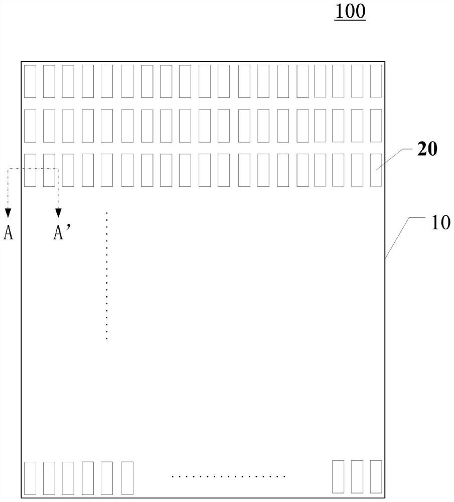
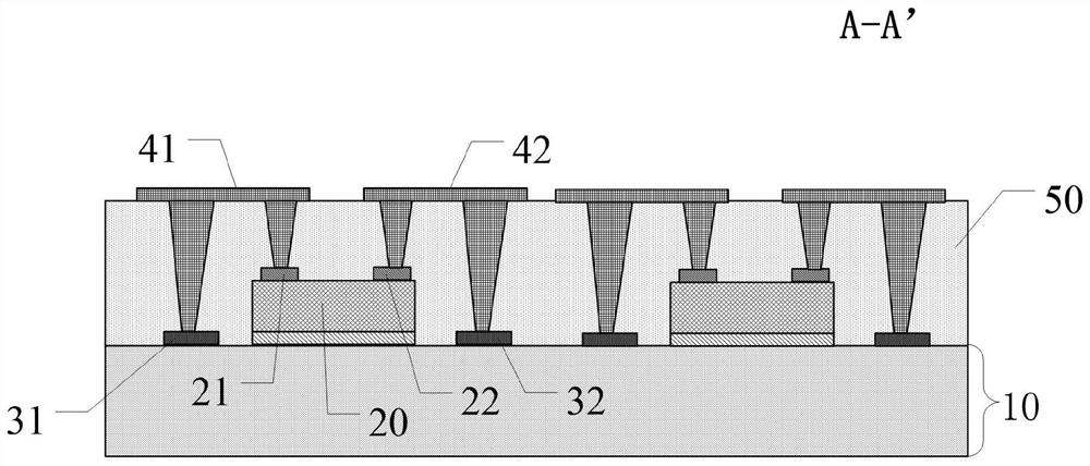
The invention discloses a display panel and a display device, which relate to the field of display technology. The display panel includes: a substrate; The electrodes are located on the side of the light-emitting element away from the substrate, and the light-emitting element emits light toward the substrate side; the first voltage terminal and the second voltage end, the first voltage end and the second voltage end are located on the side of the first electrode and the first electrode facing the substrate ; The first connection electrode and the second connection electrode, the first connection electrode and the second connection electrode are located on the side of the first electrode and the second electrode away from the light-emitting element; wherein, the first connection electrode is electrically connected to the first electrode and the first voltage terminal, and the second connecting electrode is electrically connected to the second electrode and the second voltage terminal. The light-emitting element emits light toward the base, realizes the frameless design of the display panel, improves the aperture ratio of the display panel and the display device, and facilitates the seamless splicing between the display panels.

Description

technical field [0001] The present invention relates to the field of display technology, and more particularly, to a display panel and a display device. Background technique [0002] From the era of CRT (Cathode Ray Tube, cathode ray tube) to the era of liquid crystal, and now to the era of OLED (Organic Light-Emitting Diode, organic light-emitting diode), the display industry has undergone decades of development and has changed with each passing day. The display industry has been closely related to our lives. From traditional mobile phones, tablets, TVs and PCs, to the current smart wearable devices and VR, display technology is inseparable. [0003] With the development of science and technology, in order to increase the screen ratio, the display panel has become more and more inclined to have a narrow frame design. The display panel of the prior art is usually provided with a frame area and a display area, and the frame area of ​​the display panel usually needs to be pro...

Claims


Application Information

Patent Timeline
Patent Type & Authority Patents(China)
IPC IPC(8): H01L27/32H01L51/52G09G3/3225
CPCG09G3/3225G09G2300/0426H10K59/00H10K50/805H10K2102/3023
Inventor 戴文君邢亮吴天一
Owner SHANGHAI TIANMA MICRO ELECTRONICS CO LTD
Learn More