Railway sewage suction truck side suction working device and operation method thereof

A technology of working device and sewage suction vehicle, applied in cleaning methods, track cleaning, construction, etc., can solve the problems of inability to real-time output of dirt, less dirt storage, low efficiency, etc., to achieve environmental protection and decontamination operations and solve efficiency. low effect

Pending Publication Date: 2020-04-21
CRCC HIGH TECH EQUIP CORP LTD
View PDF3 Cites 1 Cited by
  • Summary
  • Abstract
  • Description
  • Claims
  • Application Information

AI Technical Summary

Problems solved by technology

Although the arms are connected by mechanical hinges to achieve rotation, lifting, telescopic and other actions, the structure is not flexible, and manual assistance is still required to operate the suction hose to achieve precise positioning, which is time-consuming and laborious; the Chinese utility model patent publication with the patent number ZL201420049741.4 A mobile pipe arm of a sewage suction truck is developed. The multi-section mechanical arm is connected sequentially in a hinged manner, and the sewage is sent into the storage tank through the suction pipe. It can be flexibly rotated, stretched, and lifted to realize the function of auxiliary suction. , but there are still some problems that cannot be effectively solved: the suction pipe adopts the direct suction method, and the efficiency is low. Ballast, powder, etc.
At the same time, using the storage tank to directly store the dirt will cause the dust with small particles to be discharged into the atmosphere with the fan, which will affect the environment.
For the internal operation of the railway tunnel, the use of storage tanks to carry out the sewage suction operation will cause the fine dust particles to be directly discharged into the tunnel. For the flammable and explosive dust particles, it will directly bring great harm to the operators, operating equipment and the tunnel. security risks
[0006] The equipment in the above-mentioned prior art mainly relies on disc blowing, pipe vacuuming, water spraying or surrounding spraying to carry out dust suction, and can clean loose dust with a small specific gravity deposited in railway or highway tunnels, but there are The following notable defects: Affected by the speed attenuation after air diffusion, the dirt absorption capacity is weak; it is not suitable for two-way railway tunnels, and it is not suitable for tunnels with uneven or wide road surfaces; it is not suitable for dust deposition for a long time or hardening. The road surface cannot clean large solid particles; at the same time, it is driven by a motor, which is bulky; it cannot output the sucked dirt in real time, and the dirt storage is small; at the same time, the device described in the above patent is difficult to handle the distance between the two sides of the track and the drainage ditch. It is also difficult to deal with the dirt in the tunnel avoidance hole

Method used


Image

  • Railway sewage suction truck side suction working device and operation method thereof
  • Railway sewage suction truck side suction working device and operation method thereof
  • Railway sewage suction truck side suction working device and operation method thereof

Examples


Embodiment 11

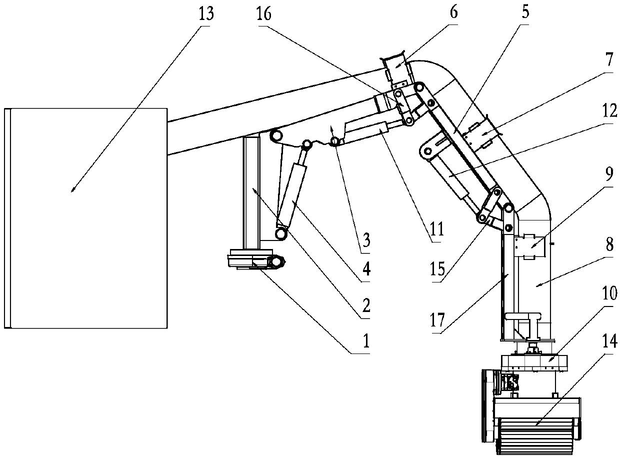
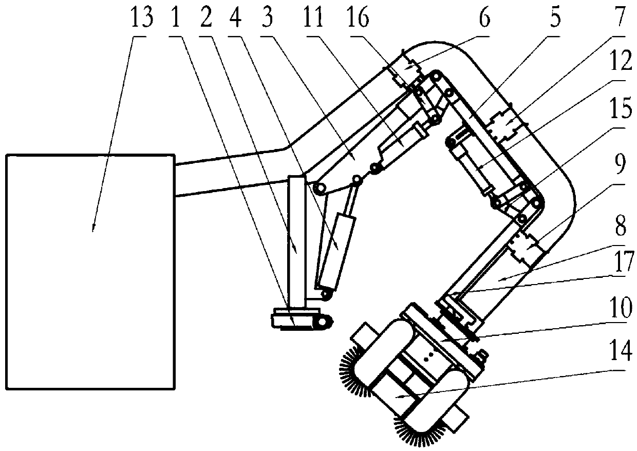
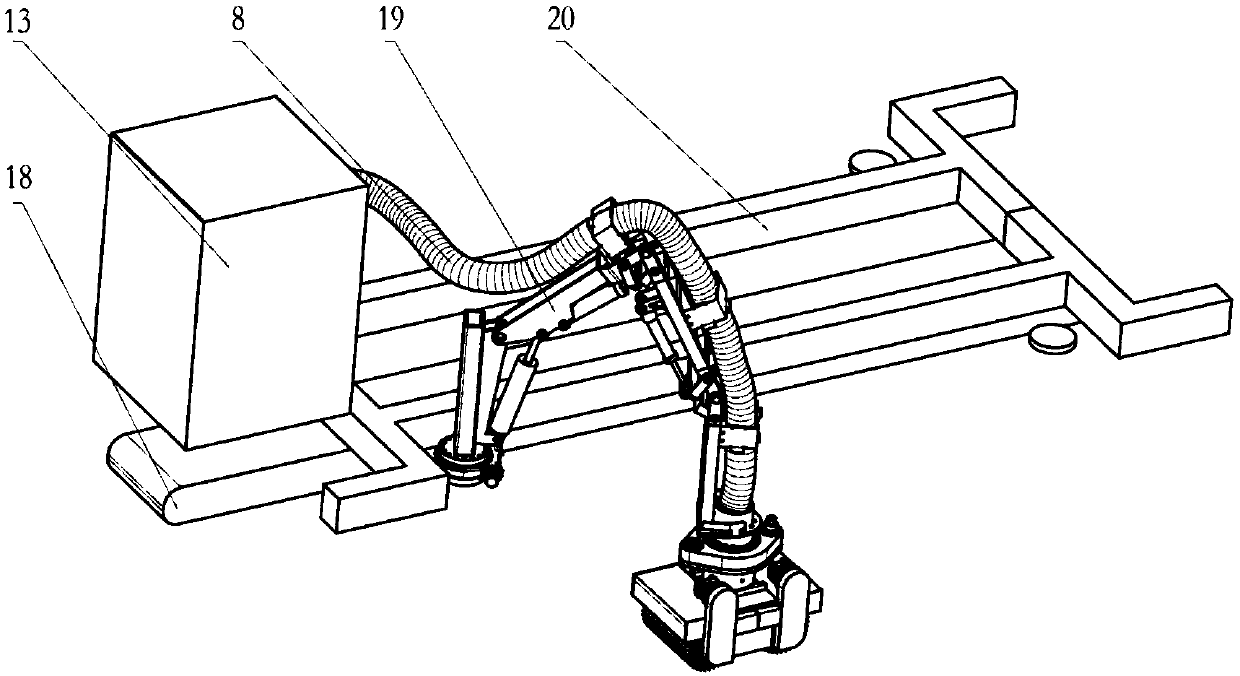
[0052] Embodiment 1.1: a kind of side suction working device of railway sewage suction truck, such as Figure 1-Figure 3 As shown, it includes a side suction operation device 19, which is connected to the dust removal device 13. The side suction operation device 19 includes a rotary support turntable 1, and the rotary support turntable 1 is fixed on the railway sewage suction vehicle frame 20. , and the rotary support turntable 1 is equipped with a rotary motor, and the rotary support turntable 1 rotates around its own vertical axis under the power of the rotary motor; the rotary support turntable 1 is equipped with a mechanical arm II 2, and the end of the mechanical arm II 2 It is hinged with one end of the mechanical arm III 3, the other end of the mechanical arm III 3 is hinged with the head end of the mechanical arm V 5, and the end of the mechanical arm V 5 is hinged with the mechanical arm VII 17; the rotary support turntable 1 is also connected with a suction pipe 8, th...

Embodiment 21

[0062] Embodiment 2.1 A side suction operation method of a railway sewage suction truck, which includes:

[0063] Step S1: Fix the rotary support turntable (1) on the frame of the sewage suction truck, and make the mechanical arm rotate around the vertical axis of the rotary support turntable (1) under the power of the rotary motor of the rotary support turntable (1) , so that the suction device (14) at the end of the suction pipe is rotated to the vicinity of the position to be operated;

[0064] Step S2: the multi-section mechanical arms on the outside of the suction pipe are connected together sequentially in an articulated manner; the end of the mechanical arm II 2 is hinged to one end of the mechanical arm III 3, and the oil cylinder is connected between the mechanical arm III 3 and the mechanical arm V 5 The support hinge VI16, the cylinder support hinge V 15 is connected between the mechanical arm V 5 and the mechanical arm VII 17;

[0065]Step S3: According to the ran...


PUM


Abstract

The invention discloses a railway sewage suction truck side suction working device which comprises a dust removal system, the outer side of the dust removal system is connected with a sweeping and sucking device (14) through a suction pipe (8); the sweeping and sucking device comprises a rotary supporting box body (27) connected to the tail end of a sucking pipe (8); a rotary support driving motor(30) is arranged on the rotary supporting box body (27); the rotary support driving motor (30) is used for driving the rotary supporting box body (27) to rotate to a required operation position; a side suction device cover body (29) is further connected to the lower portion of the rotary supporting box body (27), a motor (26) is arranged above the side suction device cover body (29), a rolling brush (25) is arranged below the side suction device cover body (29), and the upper portion of the rotary supporting box body (27) is communicated with the suction pipe (8). According to the technical scheme, operators can be greatly reduced, the manual labor intensity is reduced, and the health level of the operators is improved.

Description

technical field [0001] The invention relates to a side suction working device of a railway sewage suction vehicle, belonging to the technical field of railway machinery design and manufacture. Background technique [0002] The railway track bed sewage suction truck is used for dust removal and coal removal in tunnels. The car can clean the track bed of high-speed railways, ordinary railways and stations, absorb dust, solid debris and tiny stones deposited or adsorbed on the surface of the track bed, and ensure the cleanliness and operation of the railway. Safety, to avoid dust and sundries from polluting the air and damaging the sensors of high-speed trains, especially EMUs, to ensure safe operation of the line. [0003] The action of the coal suction car on the railway track bed includes: the running system drives the whole vehicle to travel, the main suction device is responsible for the coal removal operation in the middle part of the track bed, and the side suction devic...

Claims


Application Information

Patent Timeline
Patent Type & Authority Applications(China)
IPC IPC(8): E01H8/00E01H8/10
CPCE01H8/00E01H8/105
Inventor 袁胜万于骐玮韩双平杨兵孙荣民王深平赵强
Owner CRCC HIGH TECH EQUIP CORP LTD
Why Eureka
Try Eureka