
Yarn beating device for rope production

A rope and consistent technology, applied in the field of yarn beating devices for rope production, can solve the problems of single function and low take-up efficiency, and achieve the effect of high take-up efficiency, stable structure and function, and tight take-up

Active Publication Date: 2020-04-21
浙江省三门南方工业有限公司
View PDF6 Cites 0 Cited by
  • Summary
  • Abstract
  • Description
  • Claims
  • Application Information

AI Technical Summary

Problems solved by technology

[0003] The object of the present invention is to provide a yarn beating device for rope production in order to solve the above problems, which solves the problems of the existing rope production beating device with single function and low wire take-up efficiency

Method used

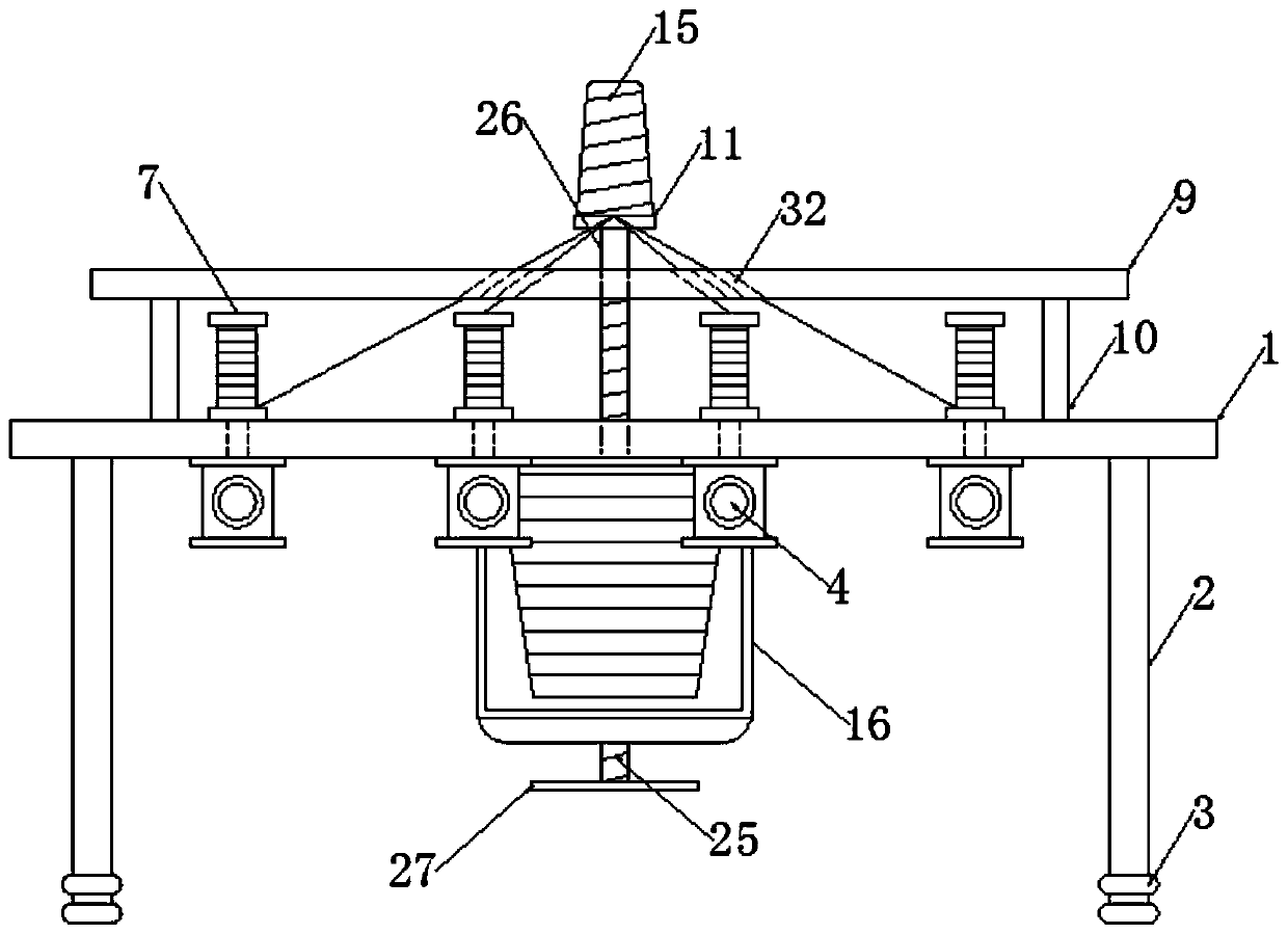

Image

  • Yarn beating device for rope production
  • Yarn beating device for rope production
  • Yarn beating device for rope production

Examples


Embodiment Construction

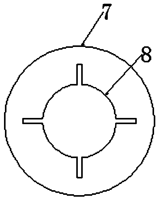
[0025] Such as Figure 1-10 As shown, this embodiment adopts the following technical solutions:

[0026] A yarn beating device for rope production, comprising a workbench 1, the workbench 1 is arranged in a disc shape, four support columns 2 are fixedly installed on the lower end surface of the workbench 1, and the specifications of the four support columns 2 are Consistent and arranged in a rectangular array with respect to the lower end surface of the workbench 1, the lower end surfaces of the four support columns 2 are all fixedly installed with feet 3, the specifications of the four feet 3 are consistent, and the lower end surface of the workbench 1 is fixedly installed with several shafts Seat 4, several shaft seats 4 have the same specifications, and are equidistant from each other with respect to the center position of the lower end surface of the workbench 1. The upper ends of several shaft seats 4 are all rotatably mounted with shaft rods 5, and several shaft seats T...


PUM


Abstract

The invention discloses a yarn beating device for rope production. The device comprises a workbench; the workbench is arranged in a disc shape; four supporting columns are fixedly mounted on the lowerend surface of the workbench; the four supporting columns are consistent in specification and are arranged in a rectangular array with respect to the lower end surface of the workbench; supporting legs are fixedly mounted on the lower end surfaces of the four supporting columns; the four supporting legs are consistent in specification; a plurality of shaft seats are fixedly mounted on the lower end surface of the workbench; the multiple shaft seats are consistent in specification; the shaft seats are equidistantly circumferentially distributed with respect to the center of the lower end surface of the workbench; shaft rods are rotatably mounted at the upper ends of the multiple shaft seats; four first limiting strips are fixedly mounted at each of rod heads of the multiple shaft rods; andthe four first limiting strips of the rod head of the same shaft rod are equidistantly circumferentially distributed with respect to the rod center of the shaft rod. The invention relates to the yarnbeating device for rope production; the yarn beating device for rope production performs winding operation by the characteristic of lifting rotation of a screw rod, and has the characteristics of stable structural function and tight winding.

Description

technical field [0001] The invention belongs to the technical field of rope production, in particular to a yarn beating device for rope production. Background technique [0002] In the production process of the rope, it is necessary to disassemble the thread for sorting and merging, so as to successfully complete the yarn beating process. The position of the take-up cylinder of the traditional yarn beating device for rope production is fixed, and it can only be taken up by a single rotation, which needs to be adjusted by height The mechanism cooperates with the thread take-up, the structure is complex and the thread take-up efficiency is low, so it is necessary to design a yarn beating device for rope production. Contents of the invention [0003] The object of the present invention is to provide a yarn beating device for rope production in order to solve the above problems, which solves the problems of single function and low wire take-up efficiency of the existing rope p...

Claims


Application Information

Patent Timeline
Patent Type & Authority Applications(China)
IPC IPC(8): D07B3/08
CPCD07B3/08
Inventor 王圣景
Owner 浙江省三门南方工业有限公司
Learn More