
Rotary labeling mechanism and labeling and ink-jet printing machine with same

A technology for labeling and labeling tubes, which is applied in the direction of labeling machines, labels, packaging, etc., and can solve problems such as disordered information order, lack of positioning, labeling, and coding functions, and inability to realize assembly line operations, etc.

Pending Publication Date: 2020-04-21
SUZHOU MEGAROBO TECH CO LTD
View PDF0 Cites 2 Cited by
  • Summary
  • Abstract
  • Description
  • Claims
  • Application Information

AI Technical Summary

Problems solved by technology

[0005] 1. It takes a long time for a single piece. When the order volume is high, the production capacity demand can only be met through manual assistance;
[0006] 2. The process is scattered, and the flow operation cannot be realized, and the sequence of information is prone to disorder in the process of manual intervention;
[0007] 3. It does not have the ability to confirm information. When the data is out of order, it can only be found through human inspection;
[0008] 4. The equipment does not have the function of positioning, labeling and inkjet coding

Method used


Image

  • Rotary labeling mechanism and labeling and ink-jet printing machine with same
  • Rotary labeling mechanism and labeling and ink-jet printing machine with same
  • Rotary labeling mechanism and labeling and ink-jet printing machine with same

Examples


Embodiment Construction

[0087] In order to make the objects, technical solutions and advantages of the present invention more apparent, exemplary embodiments according to the present invention will be described in detail below with reference to the accompanying drawings. Apparently, the described embodiments are only some embodiments of the present invention, not all embodiments of the present invention, and it should be understood that the present invention is not limited by the exemplary embodiments described here. Based on the embodiments of the present invention described in the present invention, all other embodiments obtained by those skilled in the art without creative efforts shall fall within the protection scope of the present invention.

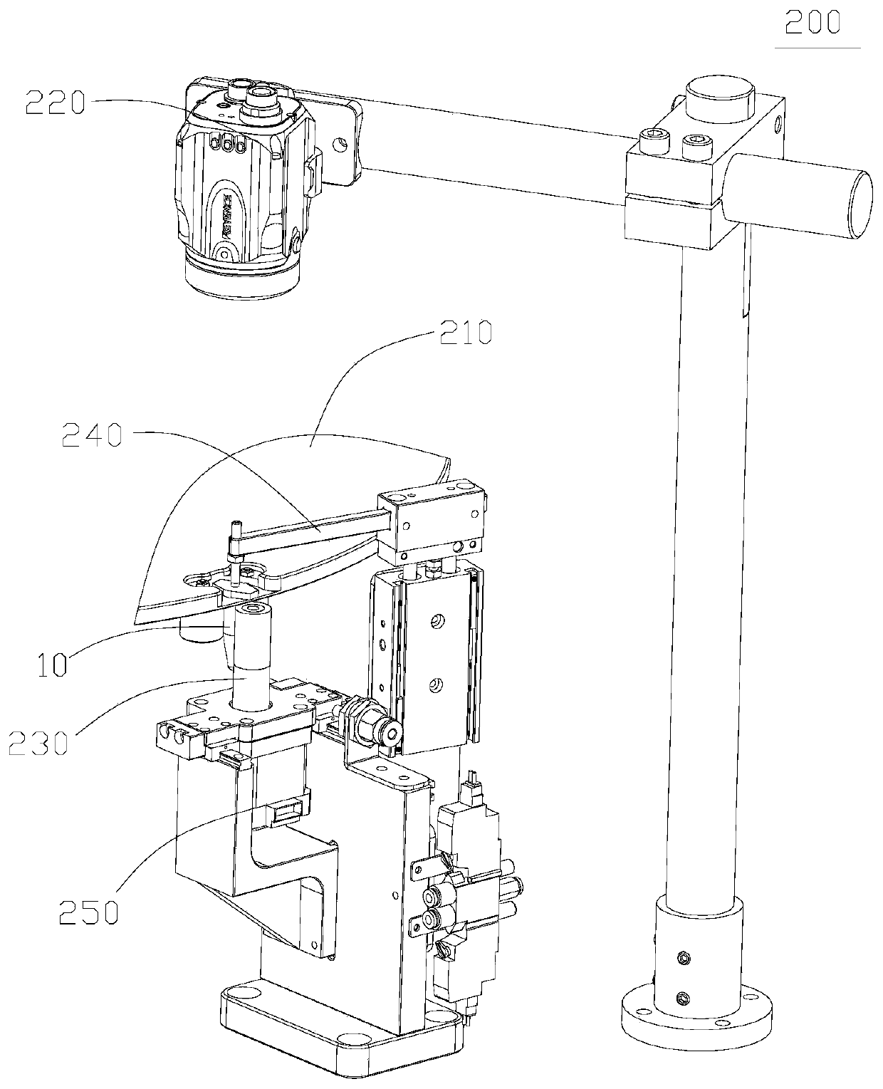
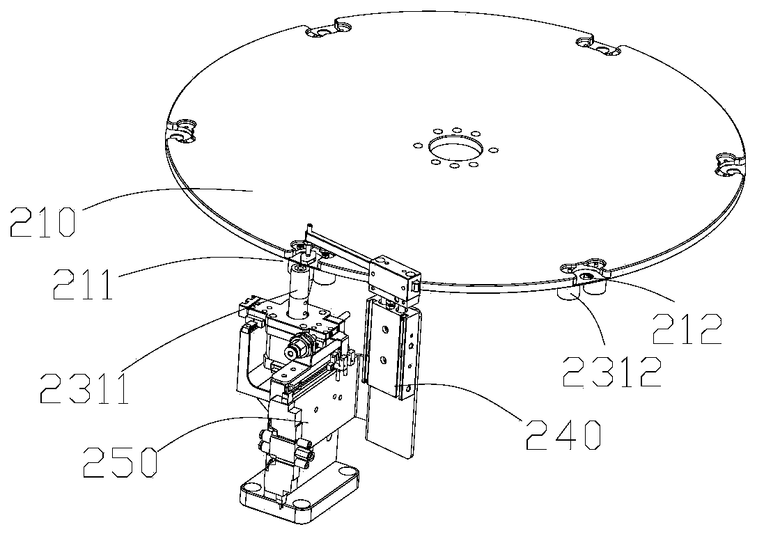
[0088] The rotary labeling mechanism is an important part of the labeling inkjet printer. The detailed structure of the rotary labeling mechanism determines whether the labeling inkjet printer can label with high precision.

[0089] combined reference F...


PUM


Abstract

The invention provides a rotary labeling mechanism and a labeling and ink-jet printing machine with the same. The rotary labeling mechanism comprises a rotating plate, a camera recognizing assembly and a labeling mechanism. The rotating plate is provided with a labeling station. The outer edge of the rotating plate is provided with a containing groove capable of containing a to-be-labeled pipe. The camera recognizing assembly comprises a camera. The camera is provided with a labeling sensor which can trigger an in-place signal when sensing a pipe cover identification position. The labeling mechanism comprises a label conveying mechanism and a roller assembly. The roller assembly comprises a label roller and a driven roller. The label roller is arranged at the labeling station. The driven roller is arranged on the rotating plate and located on the periphery of the containing groove. The label conveying mechanism conveys label paper to the labeling station on the basis of the in-place signal. The label roller is connected with a position adjusting assembly. The position adjusting assembly drives the label roller to be pressed to the to-be-labeled pipe from the side face of the to-be-labeled pipe and makes the conveyed label paper rolled and attached to the to-be-labeled pipe when the to-be-labeled pipe rotates to the labeling station along with the rotating plate. By means of therotary labeling mechanism, the label can be attached at a designated angle.

Description

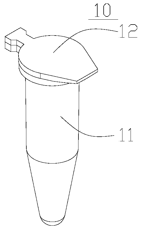
technical field [0001] The present invention relates to the technical field of labeling and inkjet coding, in particular to a rotary labeling mechanism and a labeling inkjet machine including the same. Background technique [0002] EP tube (specifically 1.5ml centrifuge tube) is a small centrifuge tube, a laboratory consumable, used in conjunction with a microcentrifuge for the separation of micro reagents, providing a new tool for micro-manipulation experiments in molecular biology . [0003] In view of the fact that some domestic research units and scientific research institutions have a small demand for mother liquor (maybe only do one or two experiments), it is necessary to make small subpackages of the mother liquor. Execution, therefore, it is necessary to carry out labeling and coding operations on EP pipes, such as figure 1 As shown, the EP tube 10 (ie, the tube to be labeled hereinafter) has a tube body 11 and a tube cover 12, the cylindrical surface of the tube b...

Claims


Application Information

Patent Timeline
IPC IPC(8): B65C9/40B65C9/42B65C9/36
CPCB65C9/36B65C9/40B65C9/42
Inventor 董洪祥王金龙丁建伟余东博
Owner SUZHOU MEGAROBO TECH CO LTD
Learn More