
Orthopedic traction device

A traction device and orthopedic technology, applied in the field of medical equipment, can solve the problems of large space occupation, large volume, inconvenient storage and transportation, etc., and achieve the effects of reducing space occupation, convenient movement and easy folding

Inactive Publication Date: 2020-04-21
靳彩霞
View PDF7 Cites 6 Cited by
  • Summary
  • Abstract
  • Description
  • Claims
  • Application Information

AI Technical Summary

Problems solved by technology

[0004] The purpose of the present invention is to solve the shortcomings of the orthopedic traction frame in the prior art that it is not easy to fold, has a large volume, takes up a large space, and is inconvenient to store and transport, and proposes an orthopedic traction device

Method used


Image

  • Orthopedic traction device
  • Orthopedic traction device
  • Orthopedic traction device

Examples


Embodiment 1

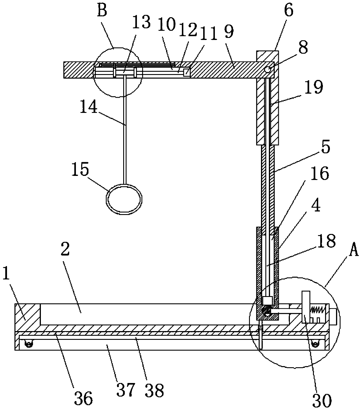
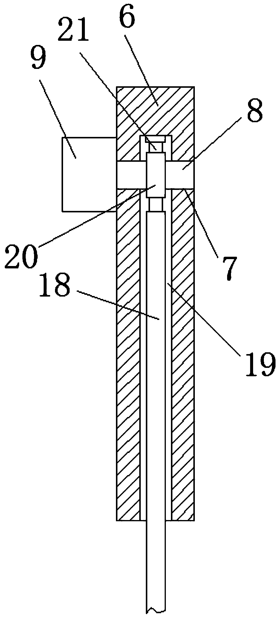
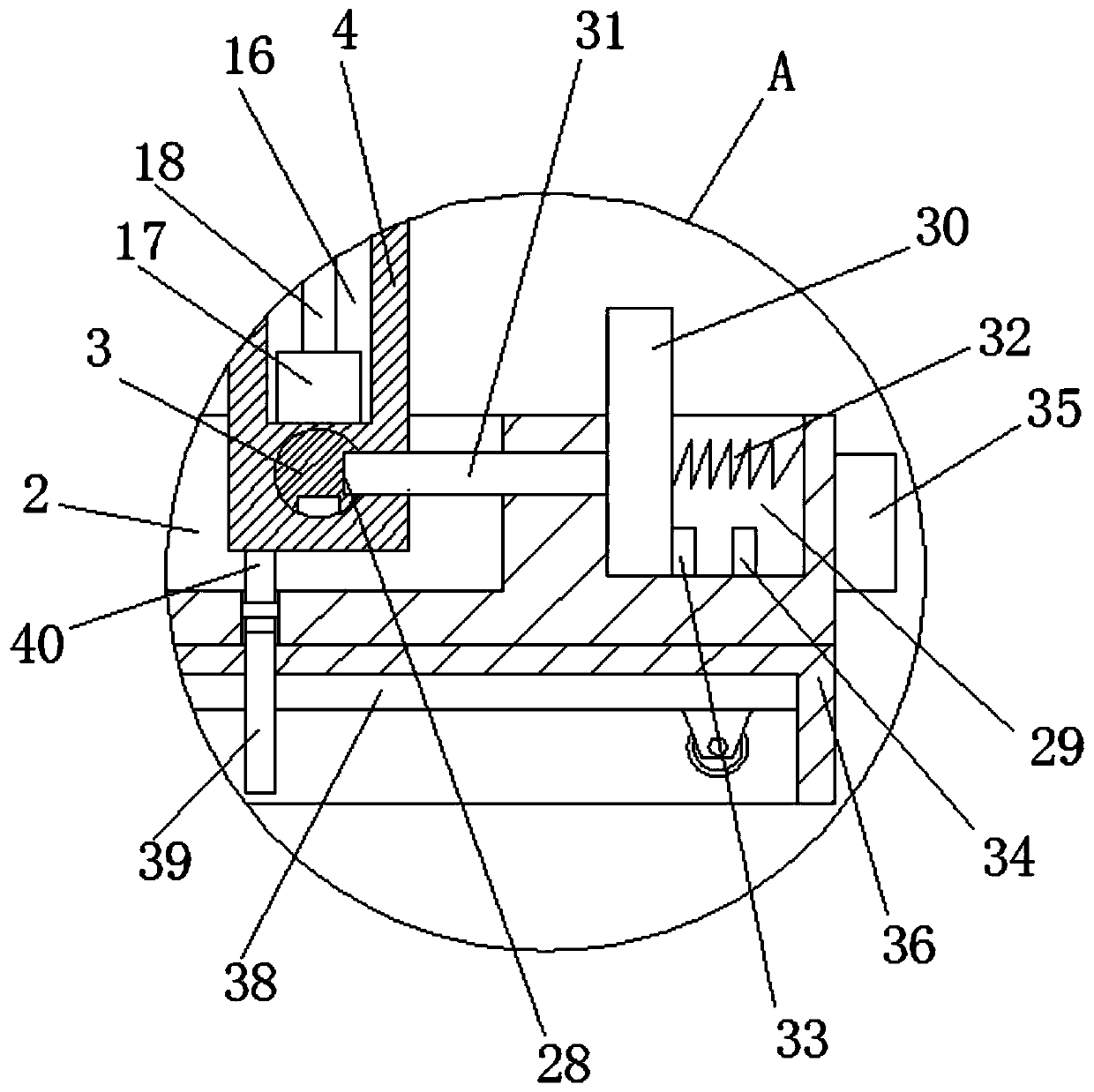
[0023] Embodiment one: refer to Figure 1-5 , an orthopedic traction device, comprising a moving seat 1, a receiving groove 2 is opened on the top of the moving seat 1, a rotating shaft 3 is installed in the receiving groove 2, and a riser 4 is fixedly installed on the outside of the rotating shaft 3, and the riser 4 The top is provided with a vertical groove 16, and a connecting plate 5 is slidably installed in the vertical groove 16, and a mounting plate 6 is fixedly installed on the top of the connecting plate 5. Column 8, one end of the rotating column 8 is fixedly installed with a horizontal plate 9, and the bottom of the horizontal plate 9 is provided with a rotating groove 10, and a first motor 11 is fixedly installed on the inner wall of one side of the rotating groove 10, and on the output shaft of the first motor 11 A rectangular rod 12 is fixedly installed, and the outer side of the rectangular rod 12 is slidably installed with a wire take-up tube 13, and one end of...

Embodiment 2

[0033] Embodiment two: refer to Figure 1-5 , an orthopedic traction device, comprising a moving seat 1, a receiving groove 2 is opened on the top of the moving seat 1, a rotating shaft 3 is installed in the receiving groove 2, and a vertical plate 4 is installed on the outer side of the rotating shaft 3 through bolts, the vertical plate The top of 4 is provided with a vertical groove 16, and a connecting plate 5 is slidably installed in the vertical groove 16. The top of the connecting plate 5 is fixed with a mounting plate 6 by bolts, and a horizontal hole 7 is provided on the mounting plate 6. A rotating column 8 is installed for rotation, and one end of the rotating column 8 is fixedly installed with a horizontal plate 9 by bolts, and the bottom of the horizontal plate 9 is provided with a rotating groove 10, and a first motor 11 is fixedly installed on the inner wall of one side of the rotating groove 10 by bolts, On the output shaft of the first motor 11, a rectangular r...


PUM


Abstract

The invention belongs to the field of medical equipment, in particular to an orthopedic traction device. In order to solve the problem that an existing traction frame for the orthopedics department isinconvenient to fold, large in size, large in occupied space and inconvenient to store and transport, the following scheme is provided. Namely, the orthopedic traction device comprises a movable base; a storage groove is formed in the top of the movable base; a rotating shaft is rotationally mounted in the storage groove; a vertical plate is fixedly mounted on the outer side of the rotating shaft; a vertical groove is formed in the top of the vertical plate; a connecting plate is mounted in the vertical groove in a sliding manner; a mounting plate is fixedly mounted at the top of the connecting plate; a transverse hole is formed in mounting plate; a rotating column is rotationally mounted in the transverse hole; a transverse plate is fixedly mounted at one end of the rotating column; anda rotating groove is formed in the bottom of the transverse plate. The position of a lifting ring can be adjusted, the use requirements of different patients can be met, folding is convenient, the occupied space is reduced, and storage and movement are convenient.

Description

technical field [0001] The invention relates to the technical field of medical equipment, in particular to an orthopedic traction device. Background technique [0002] Traction therapy is a common treatment method in orthopedics. Through the traction device, the weight of the suspension is the traction force, and the weight is the reaction force, so as to relieve muscle tension and strong contraction, restore fractures and dislocations, prevent and correct soft tissue contracture, and treat A treatment method for preoperative tissue loosening and postoperative immobilization for certain diseases. It is mainly used for the treatment of certain diseases of limbs and spine, or as a means of preoperative preparation and postoperative immobilization. [0003] The existing orthopedic traction frame is inconvenient to fold, has a large volume, takes up a large space, and is inconvenient to store and transport. Therefore, we propose an orthopedic traction device to solve the above ...

Claims


Application Information

Patent Timeline
IPC IPC(8): A61F5/042A61H1/02
CPCA61F5/042A61H1/0222A61H2201/1207
Inventor 靳彩霞翟婷婷宋红卫
Owner 靳彩霞
Learn More