Vertical cavity surface emitting laser structure and manufacturing method

A technology of vertical cavity surface emission and manufacturing method, which is applied in the field of vertical cavity surface emitting laser manufacturing, and can solve the problems of large current difference, uneven brightness of light-emitting area, affecting laser quality, etc.

Active Publication Date: 2020-04-17
深圳博升光电科技有限公司
View PDF8 Cites 3 Cited by
  • Summary
  • Abstract
  • Description
  • Claims
  • Application Information

AI Technical Summary

Problems solved by technology

Generally, there are multiple light-emitting areas on a vertical cavity surface-emitting laser. When the light-emitting areas are not electrically isolated, most of the current flows through the part with a small resistance between the positive and negative electrodes, resulting in differences in the current flowing through each light-emitting area. Larger, making the brightness of each light-emitting area uneven, affecting the quality of the vertical cavity surface emitting laser

Method used


Image

  • Vertical cavity surface emitting laser structure and manufacturing method
  • Vertical cavity surface emitting laser structure and manufacturing method
  • Vertical cavity surface emitting laser structure and manufacturing method

Examples


Embodiment Construction

[0030] The application will be further described in detail below in conjunction with the accompanying drawings and embodiments. It should be understood that the specific embodiments described here are only used to explain related inventions, rather than to limit the invention. It should also be noted that, for ease of description, only parts related to the invention are shown in the drawings.

[0031] It should be noted that, in the case of no conflict, the embodiments in the present application and the features in the embodiments can be combined with each other. The present application will be described in detail below with reference to the accompanying drawings and embodiments.

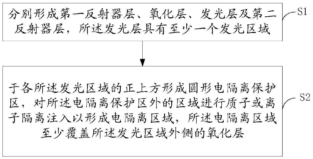
[0032] Such as figure 1 As shown, an embodiment of the present invention provides a method for manufacturing a vertical cavity surface emitting laser, including:

[0033] S1: respectively forming a first reflector layer, a light-emitting layer, an oxide layer, and a second reflector layer, the li...


PUM


Abstract

The invention discloses a vertical cavity surface emitting laser structure and a manufacturing method. The method comprises the steps: respectively forming a first reflector layer, an oxide layer, a light-emitting layer and a second reflector layer, wherein the light-emitting layer is provided with at least one light-emitting region; and forming a circular electric isolation protection region right above each light-emitting region, performing proton or ion isolation injection on the region outside the electric isolation protection region to form an electric isolation region, wherein the electric isolation region at least covers the oxide layer outside the light-emitting region. According to the scheme, the coverage area of the electric isolation region limits the flowing path of the current so that the current flows through the non-insulation region surrounded by the electric isolation region and does not flow out of the electric isolation region after the voltage is applied to the positive electrode and the negative electrode of one light-emitting region, and the reliability of the laser is improved. Meanwhile, the current flowing through each light-emitting region is uniform so that the brightness consistency of each light-emitting region is high, and the quality of the vertical cavity surface emitting laser is improved.

Description

technical field [0001] The present invention generally relates to the technical field of lasers, in particular to a method for manufacturing a vertical cavity surface emitting laser. Background technique [0002] Vertical-cavity surface-emitting laser (Vertical-Cavity Surface-Emitting Laser; VCSEL) consists of a positive electrode, a first reflector layer, a light-emitting layer, an oxide layer, a second reflector layer, and a positive electrode. When the power is turned on, a current path is formed among the positive electrode, the first reflector layer, the light-emitting layer, the second reflector layer and the positive electrode, so that the light-emitting layer emits light. Generally, there are multiple light-emitting areas on a vertical cavity surface-emitting laser. When the light-emitting areas are not electrically isolated, most of the current flows through the part with a small resistance between the positive and negative electrodes, resulting in differences in th...

Claims


Application Information

Patent Timeline
Patent Type & Authority Applications(China)
IPC IPC(8): H01S5/183H01S5/187
CPCH01S5/18308H01S5/18311H01S5/18322H01S5/187
Inventor 沈志强
Owner 深圳博升光电科技有限公司
Why Eureka
Try Eureka