
Blast furnace circulating cooling water flow regulation and control method

A technology of circulating cooling water and flow regulation, which is applied in the direction of non-electric variable control, cooling device, control/regulation system, etc., and can solve problems such as difficult to summarize the mechanism model

Active Publication Date: 2020-04-17
合肥名龙电子科技有限公司
View PDF5 Cites 0 Cited by
  • Summary
  • Abstract
  • Description
  • Claims
  • Application Information

AI Technical Summary

Problems solved by technology

[0003] However, blast furnace ironmaking is a very complex physical and chemical process, and its furnace wall temperature is affected by many factors, and it is difficult to summarize a specific and credible mechanism model
As a result, in the current known technical solutions, the flow control of the circulating cooling water of the blast furnace fails to provide an adjustment means that not only meets the cooling requirements of the furnace wall, but also saves the energy consumption of the circulating cooling water as much as possible. Rely on the long-term experience accumulation and subjective feelings of on-site engineering and technical personnel

Method used


Image

  • Blast furnace circulating cooling water flow regulation and control method
  • Blast furnace circulating cooling water flow regulation and control method
  • Blast furnace circulating cooling water flow regulation and control method

Examples


Embodiment Construction

[0061] The present invention will be further described below in conjunction with the accompanying drawings and embodiments.

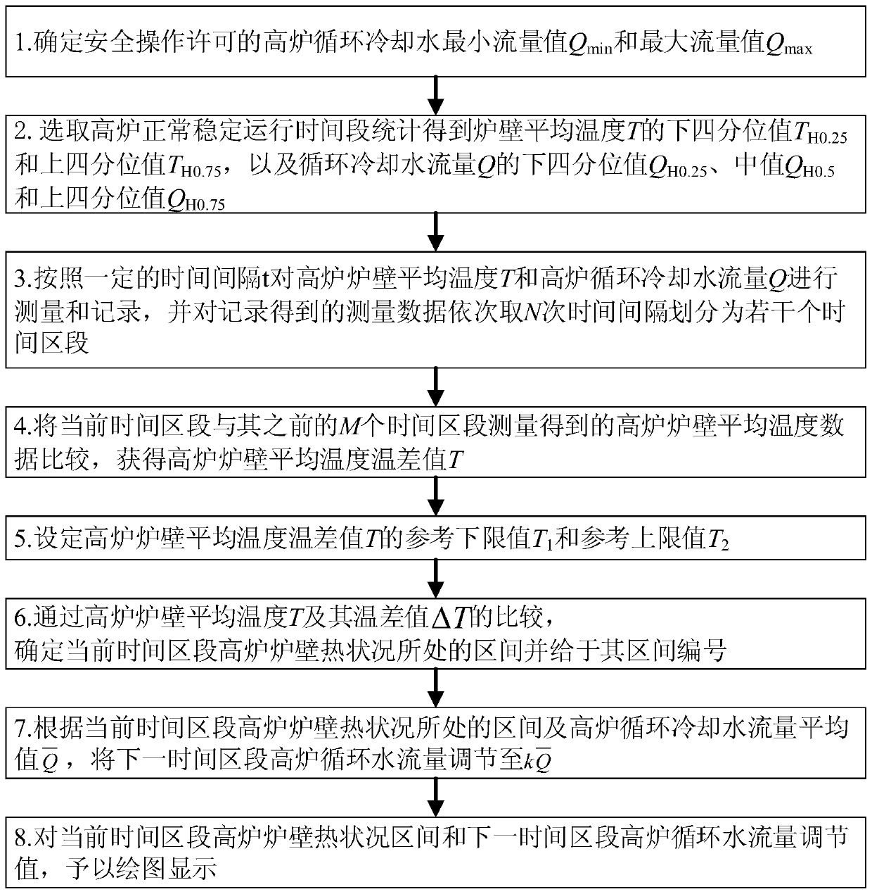
[0062] see figure 1 , is a flow chart of the inventive method, and it comprises the following steps:

[0063] Step 1. According to the process design and equipment selection information, determine the minimum flow value Q of blast furnace circulating cooling water permitted for safe operation min and the maximum flow value Q max .

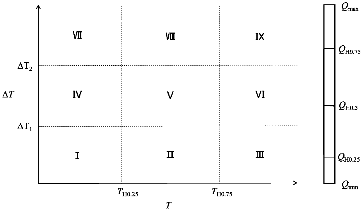
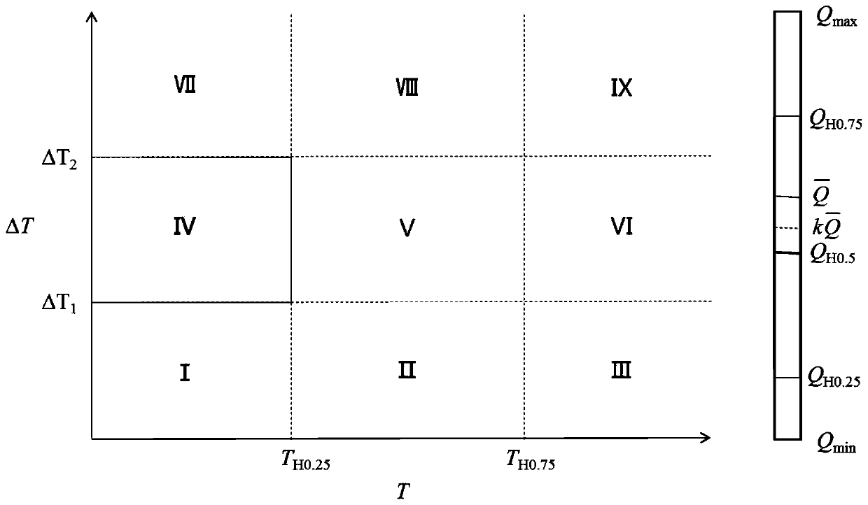
[0064] Step 2. According to the historical operation data of the blast furnace, select the normal and stable operation period of the blast furnace to obtain the lower quartile value T of the average temperature T of the blast furnace wall H0.25 and the upper quartile T H0.75 , and the lower quartile value Q of the blast furnace circulating cooling water flow Q H0.25 , median Q H0.5 and the upper quartile Q H0.75 ;

[0065] The average temperature T of the furnace wall of the blast furnace is the average value of the ...


PUM


Abstract

The invention discloses a blast furnace circulating cooling water flow regulation and control method. The method comprises steps of determining the maximum value of the blast furnace circulating cooling water; obtaining a blast furnace wall average temperature and a circulating water flow statistical distribution value according to historical operation data; measuring and recording the blast furnace wall average temperature and the circulating water flow, and dividing time sections; comparing the average temperature data of a blast furnace wall of a current time zone with the average temperature data of the blast furnace wall of the previous M time zones to obtain difference values; setting reference upper and lower limit values of the average temperature difference value of the blast furnace wall; determining an interval in which the blast furnace wall thermal condition is located in the current time interval; and adjusting the blast furnace circulating water flow in the next time section to plot and display the blast furnace wall thermal condition and the circulating water flow. The blast furnace circulating cooling water flow regulation and graphical representation method has advantages of stability, reliability, high efficiency, energy conservation, flexible response, simplicity and intuition, is beneficial to programming implementation, and is beneficial to instant observation and data understanding of field operators.

Description

technical field [0001] The invention belongs to the technical field of blast furnace circulating cooling water systems, and in particular relates to a method for adjusting and controlling the flow of blast furnace circulating cooling water. Background technique [0002] The blast furnace is the core equipment for industrial large-scale ironmaking, and its safe, stable and efficient operation is of vital significance to the ironmaking process. Since the temperature of the melt in the blast furnace ironmaking process is extremely high, usually above 1300°C, in order to protect the blast furnace wall from being damaged by high temperature, it is necessary to use a circulating cooling water system to cool the blast furnace wall. In blast furnace production, the temperature of the blast furnace wall is required to be within a reasonable range. If the temperature is too high, it will cause thermal damage to the furnace wall and affect its service life; if the temperature is too lo...

Claims


Application Information

Patent Timeline
IPC IPC(8): G05D27/02C21B7/10
CPCC21B7/10G05D27/02
Inventor 张翮辉李坤
Owner 合肥名龙电子科技有限公司
Learn More