Machine tool seat with damping and cushioning mechanism

A technology of cushioning mechanism and machine bed, which is applied in the direction of manufacturing tools, non-rotational vibration suppression, metal processing machinery parts, etc., can solve the problems of increasing noise, affecting processing effect, affecting processing accuracy, etc., to achieve convenient replacement and maintenance, and improve processing effect , good effect

Inactive Publication Date: 2020-04-17
曹玉生
View PDF0 Cites 7 Cited by
  • Summary
  • Abstract
  • Description
  • Claims
  • Application Information

AI Technical Summary

Problems solved by technology

[0002] In the existing machine tool, the outriggers are generally installed at the bottom, and the outriggers are straightened by adjusting the outriggers, and there are no other damping devices, so that a large amount of vibration will be generated during operation, which will affect the processing effect and increase the noise. generate noise pollution
[0003] At the same time, the movement between the installation platform of the existing machine tool and the machine bed is realized through slide rail lubrication, which needs to add a large amount of lubricating oil to reduce wear and tear. However, when the operator does not operate according to the regulations and the oil is not enough, it is easy to Wear and tear will affect the machining accuracy, so that the relevant parts of the whole equipment need to be replaced, or even the replacement of the whole equipment, the cost is high

Method used


Image

  • Machine tool seat with damping and cushioning mechanism
  • Machine tool seat with damping and cushioning mechanism
  • Machine tool seat with damping and cushioning mechanism

Examples


Embodiment

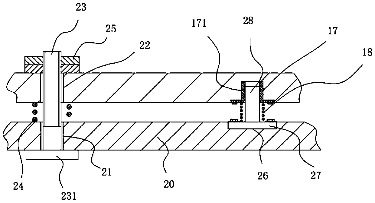
[0021] Example: see Figure 1 to Figure 3 As shown, a machine bed with a damping and buffering mechanism includes a machine base body 10, a lower horizontal support plate 20 is provided below the fixed bottom plate of the machine base main body 10, and a support is fixed on the edge of the lower horizontal support plate 20. leg assembly 30;

[0022] The edge of the lower horizontal support plate 20 is formed with a plurality of lower through holes 21, and the edge of the fixed bottom plate of the base body 10 is formed with a plurality of upper through holes 22, and the upper through holes 22 and the lower through holes 21 are aligned up and down. The adjusting stud 23 is inserted into the corresponding upper through hole 22 and the lower through hole 21, and the middle part of the adjusting stud 23 is inserted with a damping spring 24, and the bottom end of the damping spring 24 focuses on the top of the lower horizontal support plate 20. On the surface, the top of the dampi...


PUM


Abstract

The invention discloses a machine tool seat with a damping and cushioning mechanism. The machine tool seat comprises a machine seat main body; a lower horizontal supporting plate is arranged below a fixed bottom plate of the machine seat body main body; a supporting leg device is fixed on the side of the lower horizontal supporting plate; a plurality of lower through holes are molded in the side of the lower horizontal supporting plate; a plurality of upper through holes are molded in the side of the fixed bottom plate of the machine seat main body; the upper through holes are aligned with thelower through holes up and down; adjusting studs are arranged in the corresponding upper through holes and lower through holes in an inserting and sleeving manner; damping springs are arranged in themiddle of the adjusting studs in an inserting and sleeving manner; through the damping springs and a middle cushioning spring, the damping effect is realized, and the processing effect is improved; meanwhile, a detachable wear-proof lubricating plate and an inner wear-proof lubricating plate are used, so that a mounting platform cannot be in direct contact with an extending wallboard; and when being worn, the wear-proof lubricating plate and the inner wear-proof lubricating plate can be replaced, and therefore, the replacing and maintaining are convenient, and the effect is good.

Description

technical field [0001] The invention relates to the technical field of machine tool equipment, in particular to a machine bed with a vibration damping and buffering mechanism. Background technique [0002] In the existing machine tool, the outriggers are generally installed at the bottom, and the outriggers are straightened by adjusting the outriggers, and there are no other damping devices, so that a large amount of vibration will be generated during operation, which will affect the processing effect and increase the noise. Generate noise pollution. [0003] At the same time, the movement between the installation platform of the existing machine tool and the machine bed is realized through slide rail lubrication, which needs to add a large amount of lubricating oil to reduce wear and tear. However, when the operator does not operate according to the regulations and the oil is not enough, it is easy to Wear and tear will affect the machining accuracy, so that the relevant p...

Claims


Application Information

Patent Timeline
Patent Type & Authority Applications(China)
IPC IPC(8): F16F15/04B23Q1/01B23Q11/12
CPCB23Q1/015B23Q11/0032B23Q11/12F16F15/04
Inventor 曹玉生
Owner 曹玉生
Why Eureka
Try Eureka