Vehicle urea feeding device

A technology of feeding device and urea for vehicles is applied in the directions of transportation and packaging, dissolving, mixer, etc., which can solve the problems of waste of labor cost, low efficiency, time-consuming and laborious operation, etc., and achieves convenient feeding bracket, convenient moving, and convenient use. Effect

Inactive Publication Date: 2020-04-17
天蓝素(十堰)汽车环保科技有限公司
View PDF0 Cites 0 Cited by
  • Summary
  • Abstract
  • Description
  • Claims
  • Application Information

AI Technical Summary

Problems solved by technology

Ordinary feeding methods require special personnel to wait for feeding when producing urea solution, resulting in very low feeding efficiency and wasting labor costs, which cannot meet the current needs of mass production and affect work efficiency. The solution usually uses bagged raw materials, seal and open the raw material bag and connect it to the feeding port of the feeding device, then lift the raw material bag up to make the bag mouth upside down, so that the raw materials in the raw material bag will automatically enter under the action of gravity Vehicle urea machine
The existing vehicle urea machine feeding mechanism is usually manually operated. The raw material bag is too heavy, and the workers are unstable when loading the material, which leads to difficulty in feeding the material, time-consuming and laborious operation, low efficiency, and easy leakage of raw materials, resulting in serious waste of raw materials. , the cost of making urea solution for vehicles is high, and it will pollute equipment and the environment, and the cleaning operation will waste manpower and material resources

Method used


Image

  • Vehicle urea feeding device
  • Vehicle urea feeding device
  • Vehicle urea feeding device

Examples


Embodiment Construction

[0023] The following will clearly and completely describe the technical solutions in the embodiments of the present invention with reference to the accompanying drawings in the embodiments of the present invention. Obviously, the described embodiments are only some, not all, embodiments of the present invention. Based on the embodiments of the present invention, all other embodiments obtained by persons of ordinary skill in the art without making creative efforts belong to the protection scope of the present invention.

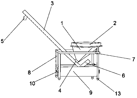
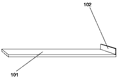
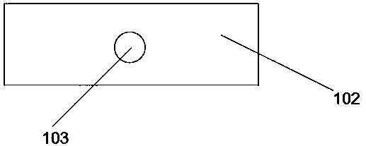
[0024] see Figure 1~Figure 4 , the present invention provides a technical solution: a vehicle urea feeding device, comprising a feed box 1, a feed port 2, a feed pipe 3, a discharge port 4, a discharge port 5, a feed motor 6, a feed Support 7, support leg 8, side plate 9, support slide plate 10, first chute 11, second chute 12 and universal wheel 13, one side of loading box 1 is fixed on the loading bracket 7, and loading bracket 7 The four corners below are...


PUM


Abstract

The invention discloses a vehicle urea feeding device. According to the vehicle urea feeding device, one side of a feeding box is fixed to a feeding support; supporting legs are arranged at the four corners of the lower portion of the feeding support; a side plate is arranged between each pair of supporting legs; first sliding grooves are formed in the middles of the inner sides of the side plates; second sliding grooves are formed in the middles of the inner sides of the supporting legs; a supporting sliding plate is arranged between each pair of a first sliding groove and a second sliding groove; a feeding opening is formed in the upper portion of the feeding box; the lower portion of the feeding box is of a conical structure, a discharging port is formed in the bottom end of the feedingbox and connected with the side wall of the feeding pipe, the feeding pipe is obliquely arranged at the lower end of the discharging port, a material discharging port is formed below the top end of the feeding pipe, a feeding motor is arranged at the tail end of the feeding pipe, the feeding motor is electrically connected with the feeding pipe, and universal wheels are arranged at the lower partof the feeding support. The supporting sliding plates are arranged below the feeding support, the supporting sliding plate is pulled out in the feeding process, an operator can conveniently place a vehicle urea raw material bag or a vehicle urea raw material barrel on the supporting sliding plate, and the problem that raw materials leak out when urea raw materials are poured into the feeding boxis avoided.

Description

technical field [0001] The invention relates to the technical field of urea feeding equipment for vehicles, in particular to a urea feeding device for vehicles. Background technique [0002] The existing urea machine needs to manually add urea particles for vehicles before each mixing of urea solution for vehicles, that is, add urea particles once and stir once, and then manually add again when the next stirring is performed. Ordinary feeding methods require special personnel to wait for feeding when producing urea solution, resulting in very low feeding efficiency and wasting labor costs, which cannot meet the current needs of mass production and affect work efficiency. The raw material in the bag is usually used for the solution, the raw material bag is sealed and opened, and then connected to the feeding port of the feeding device, and then the raw material bag is lifted up to make the bag mouth upside down, so that the raw material in the raw material bag enters automati...

Claims


Application Information

Patent Timeline
Patent Type & Authority Applications(China)
IPC IPC(8): B01F15/02
CPCB01F35/717
Inventor 严伟
Owner 天蓝素(十堰)汽车环保科技有限公司
Why Eureka
Try Eureka