


Quick Research
Generate reliable direction feasibility study reports for your R&D in just a few steps.

Technical Q&A
Discover and master advanced knowledge NOW. Basics, ideas, possibilities, all at once.

Find Solutions
As an expert in R&D theories, this can generate solutions to your technical problems instantly.

Evaluate Feasibility
Analyze your overall solution with one click, know your potential R&D risks in advance.

Monitor Landscape
Get weekly tech updates, stay abreast of the latest tech innovations and key insights.
Novel junction box
A junction box, a new type of technology, applied in the direction of electrical components, etc., can solve the problems of inability to complete re-fixation, exposed hinges, inconvenient fixation, etc.
- Summary
- Abstract
- Description
- Claims
- Application Information
AI Technical Summary
Problems solved by technology
Method used
Image

Examples
Embodiment 1
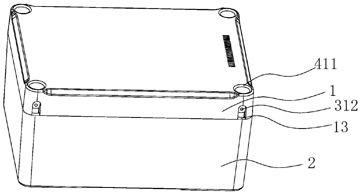
[0050] Refer to attached Figure 1-15 As shown, a junction box includes an upper cover 1, a base 2, a dual-purpose board 4 and fasteners 3, the upper cover 1 and the base 2 form a cavity 11, and the fasteners are used to connect and fix the upper cover 1 and the The base 2 and the double-purpose board 4 are fixed in the accommodation cavity 11, so that the interior forms an isolation effect. Its specific structure is shown below.
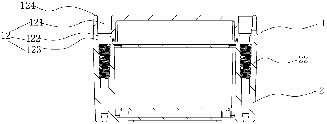
[0051] The upper cover 1 is provided with a first fixing hole 12, the first fixing hole 12 includes a first channel 121, a connecting channel 122 and a second channel 123, the first channel 121 is connected to the second channel 123 through the connecting channel 122, the first channel 121 is close to the top of the upper cover 1, the second passage 123 is near the end of the base 2, and the size of the first passage 121 is larger than the size of the second passage 123, so that the first fixed hole 12 is formed as a whole, and the side of the conn...
Embodiment 2
[0068] Refer to attached Figure 16-18 As shown, the difference between embodiment 2 and embodiment 1 is that at least one connecting piece 9 and connecting bolt 8 are also included, and the number of connecting piece 9 in this embodiment is one.
[0069] A first annular rib 91 is provided on the top end of the connector 9 , and a first annular groove 92 is provided on the bottom end of the connector 9 . Four fifth fixing holes 93 are provided on the connecting member 9 , and bosses 931 are arranged in the fifth fixing holes 93 .
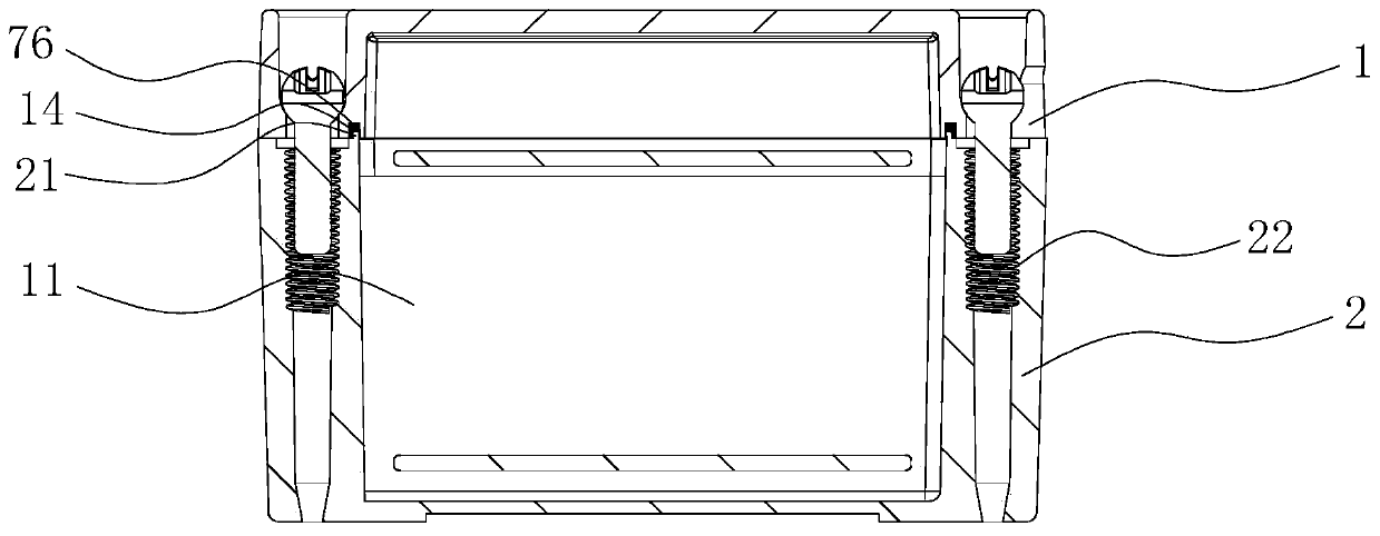
[0070] Here, when the base 2 is matched with the upper cover 1 through the connecting piece 9 , the first annular rib 91 is inserted into the second annular groove 14 , and the second annular rib 21 is embedded into the first annular groove 92 . Further, the first gasket 75 is fixed on the first annular groove 92 , and the second gasket 76 is fixed on the second annular groove 14 . Here, the second gasket 76 is arranged in steps, and the arrangeme...
Embodiment 3
[0075] Refer to attached Figure 19 As shown, the difference between Embodiment 3 and Embodiment 2 is that the number of connecting pieces 9 is three. The connecting piece 9 is fixed with the connecting piece 9 by connecting bolts 8 to realize the height adjustment of the base 2 and the upper cover 1 . Since the structures of the connecting piece 9 and the connecting bolt 8 have been described in detail here, no more details are given here.
PUM
 Abstract
Description
Claims
Application Information
 - R&D Engineer
- R&D Manager
- IP Professional
- Industry Leading Data Capabilities
- Powerful AI technology
- Patent DNA Extraction
Browse by: Latest US Patents, China's latest patents, Technical Efficacy Thesaurus, Application Domain, Technology Topic, Popular Technical Reports.
© 2024 PatSnap. All rights reserved.Legal|Privacy policy|Modern Slavery Act Transparency Statement|Sitemap|About US| Contact US: help@patsnap.com