
Systems and method for hazardous waste incineration

A technology for hazardous waste and feeding system, applied in the field of hazardous waste incineration systems, can solve the problems of strong flue gas corrosiveness, inability to effectively dispose of hazardous waste, and difficult processing.

Inactive Publication Date: 2020-04-14
CECEP CLEAN TECH DEV CO LTD
View PDF6 Cites 6 Cited by
  • Summary
  • Abstract
  • Description
  • Claims
  • Application Information

AI Technical Summary

Problems solved by technology

[0004] Due to the increasing production of hazardous waste enterprises year by year, the problem of disposal of hazardous waste with high sulfur, chlorine and fluorine content (Cl≤15wt%, S≤5wt%, F≤1wt%) is becoming more and more serious, and the traditional disposal process cannot be effective without reasonable compatibility. Disposal of this kind of hazardous waste, and the flue gas produced by the incineration of hazardous waste with high sulfur, chlorine, and fluorine content is highly corrosive, and has high requirements for refractory materials and various equipment. At the same time, the flue gas contains a relatively high concentration of SO X , it is difficult to handle
In addition, according to the requirements of HJ / T176-2005 "Technical Specifications for the Construction of Centralized Incineration and Disposal of Hazardous Wastes", waste heat boilers shall not be used to cool down the incineration system of hazardous wastes with high fluorine content or chlorine content greater than 5wt%.

Method used


Image

  • Systems and method for hazardous waste incineration

Examples


Embodiment Construction

[0090] The technical solutions and effects of the present invention will be further described below through specific embodiments. The following embodiments are only used to illustrate the content of the present invention, and the present invention is not limited to the following embodiments or examples. Simple changes made to the present invention by applying the concept of the present invention are all within the scope of protection of the present invention.

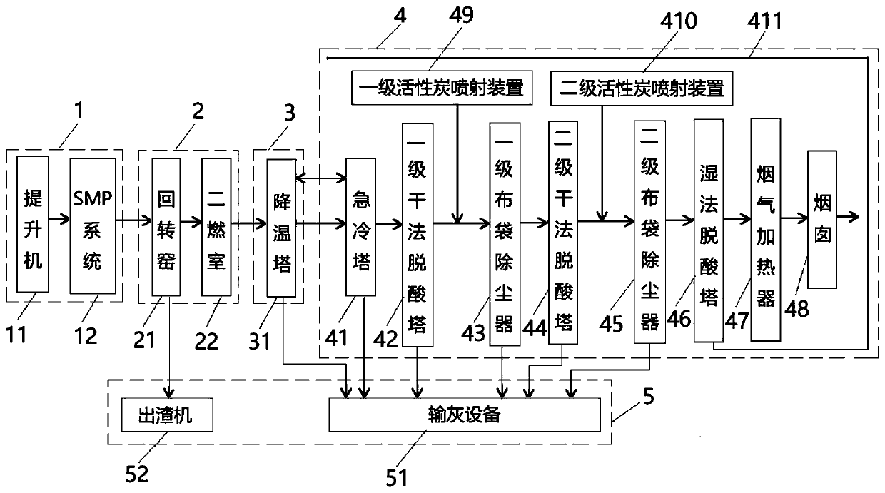
[0091] Such as figure 1 As shown, the system for hazardous waste incineration of the present invention includes a feeding system 1, an incineration system 2, a cooling system 3 and a flue gas treatment system 4 arranged in sequence;

[0092] The feeding system 1 includes a hoist 11 and an SMP system 12 arranged in sequence;

[0093] The hoist 11 is used to lift the hazardous waste to be treated to the SMP system 12;

[0094] The SMP system 12 includes a crusher, a mixer and a plunger pump arranged in sequence, for cr...


PUM


Abstract

The invention provides a system and a method for hazardous waste incineration. The system comprises a feeding system, an incineration system, a cooling system and a flue gas treatment system which aresequentially arranged; the feeding system comprises an elevator and an SMP system which are arranged in sequence; the incineration system comprises a rotary kiln and a secondary combustion chamber which are sequentially communicated, and is used for sequentially pyrolyzing fed materials twice until the fed materials are completely pyrolyzed to obtain double-pyrolyzed flue gas; the cooling systemcomprises a cooling tower and is used for cooling the double-pyrolyzed flue gas to obtain cooled flue gas; the flue gas treatment system comprises a quench tower, a first-stage dry deacidification tower, a first-stage bag-type dust collector, a second-stage dry deacidification tower, a second-stage bag-type dust collector, a wet deacidification tower, a flue gas heater, a chimney and a first-stageactivated carbon spraying device which are connected in sequence, and further comprises a first-stage activated carbon spray device used for carrying out a series of treatments on the cooled flue gasand completely discharging the treated flue gas. The method uses the system to incinerate hazardous wastes. The system and the method can be used for incinerating hazardous wastes with high sulfur, chlorine and fluorine contents.

Description

technical field [0001] The invention belongs to the field of hazardous waste treatment, in particular to a system and method for hazardous waste incineration. Background technique [0002] Hazardous waste refers to "waste with hazardous characteristics that is included in the national list of hazardous waste or identified in accordance with the national hazardous waste identification standards and identification methods." Different hazardous wastes are disposed of by incineration, landfill, materialization, comprehensive utilization and other disposal methods according to their characteristics. Among them, hazardous wastes with high organic content and high calorific value are disposed of by incineration. [0003] In the prior art, the process plan process widely used in the incineration of hazardous waste is "feeding system + rotary kiln + secondary combustion chamber + waste heat boiler + flue gas quenching + dry deacidification + activated carbon injection + bag dust remo...

Claims


Application Information

Patent Timeline
IPC IPC(8): F23G5/16F23G5/44F23G5/46F23J15/02F23J15/04F23J15/06
CPCF23G5/16F23G5/44F23G5/46F23J15/025F23J15/04F23J15/06
Inventor 李琪刘东风施耀华亓淑红邓丹丹吴磊张蕊薛镜徽宋越李彬彬陈振华邱晨张博蔡增宅邹良栋
Owner CECEP CLEAN TECH DEV CO LTD
Learn More