
Vehicle by using blowing type heat dissipation device

A heat dissipation device and vehicle technology, applied in the field of vehicles, can solve the problems of damaging electric fans and affecting heat dissipation effects, etc.

Pending Publication Date: 2020-04-14
ZHENGZHOU YUTONG BUS CO LTD
View PDF1 Cites 0 Cited by
  • Summary
  • Abstract
  • Description
  • Claims
  • Application Information

AI Technical Summary

Problems solved by technology

[0004] The purpose of the present invention is to provide a vehicle using a blowing heat dissipation device, which is used to solve the problem that the hot air blown out by the radiator flows back into the cold air flow generated by the electric fan when the heat dissipation device in the existing vehicle is working, which affects the heat dissipation effect and damages the electric motor. Problems with fan electronics

Method used


Image

  • Vehicle by using blowing type heat dissipation device
  • Vehicle by using blowing type heat dissipation device
  • Vehicle by using blowing type heat dissipation device

Examples


Embodiment Construction

[0032] The specific embodiments of the present invention will be further described below in conjunction with the accompanying drawings.

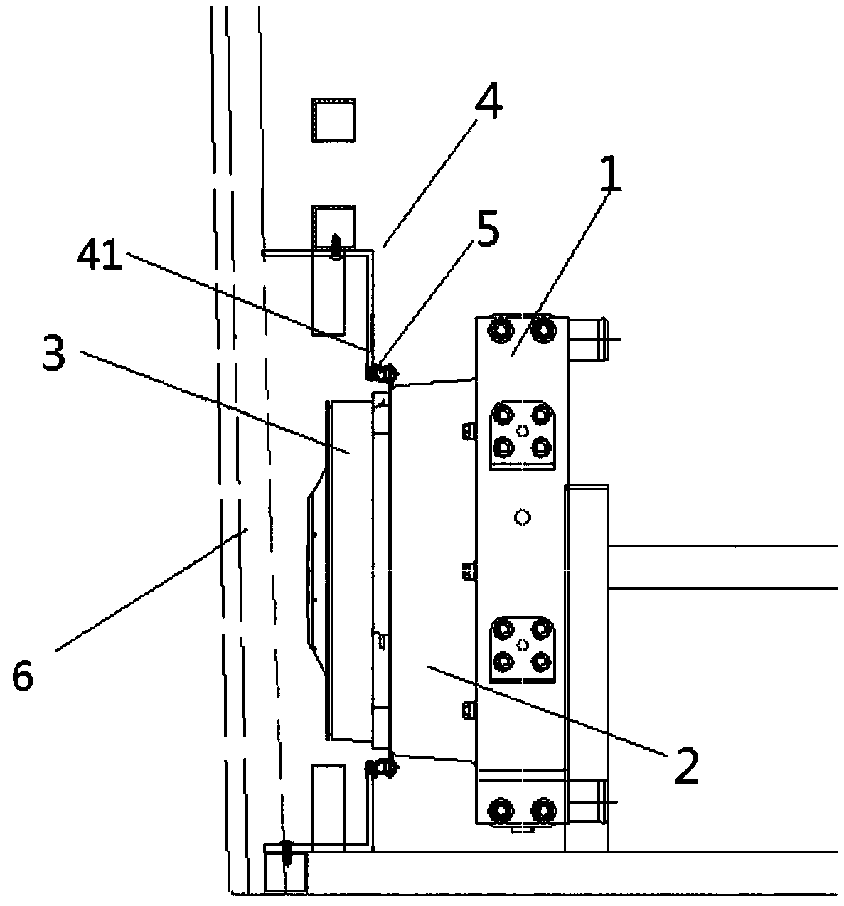
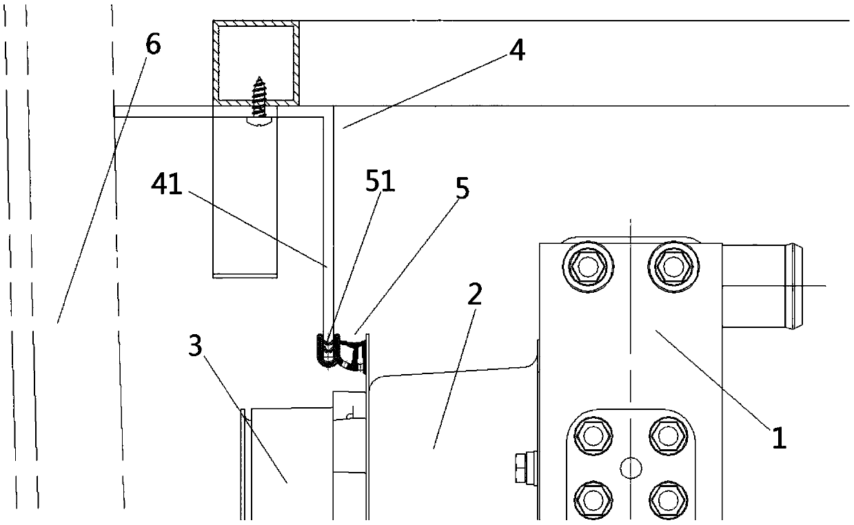
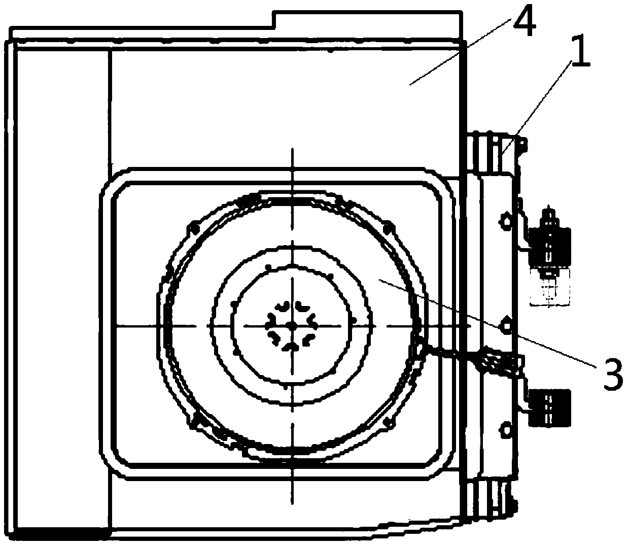
[0033] Such as figure 1 with figure 2 As shown, the first embodiment of the vehicle using the blowing type heat sink of the present invention is an electric vehicle, which includes a power unit, a heat sink for dissipating heat from the power unit, and a heat sink for drawing air from the outside. The air inlet hatch 6. Of course, in other embodiments, the vehicle may also be a fuel vehicle.

[0034] Such as Figure 1~Figure 10 As shown, the above-mentioned heat dissipation device includes a radiator 1 connected with a power unit through a water pipe to form a water flow circuit. A windshield 2 is fixedly installed on the radiator 1 by bolts. The windshield 2 is a cylindrical structure. The end connected to the radiator 1 is the radiator mounting surface 21, the other end of the windshield 2 is the electric fan mounting surface 22, the electric...


PUM


Abstract

The invention relates to a vehicle by using a blowing type heat dissipation device. The vehicle comprises a power unit and a heat dissipation device used for dissipating heat of the power unit. The vehicle is further provided with an air inlet cabin door allowing the heat dissipation device to suck air from the outside. The heat dissipation device comprises a radiator and an electric fan; a fan cover is fixedly mounted on one side of the radiator; one port of the fan cover corresponds to the radiator; the electric fan is installed at the other end of the fan cover and is close to the air inletcabin door, a sealing cover is further fixedly arranged on the vehicle relative to the fan cover, one port of the sealing cover is directly or indirectly communicated with a door opening of the air inlet cabin door, and the other end of the sealing cover is in sealing fit with the electric fan or the fan cover so that a sealed air passing channel can be formed between the air inlet cabin door andthe radiator. The vehicle using the air blowing type heat dissipation device can be used for solving the problems that when a heat dissipation device in an existing vehicle works, hot air blown out of the heat dissipation device flows back into cold air flow generated by the electric fan, the heat dissipation effect is affected, and electronic elements of the electric fan are damaged.

Description

Technical field [0001] The invention relates to a vehicle using a blower type heat dissipation device. Background technique [0002] The power unit on the vehicle generates a lot of heat during operation, and the high temperature of the power unit will affect its performance and life. In order to ensure the normal use of the power unit, a heat sink is usually used to reduce the temperature of the power unit. For example, a Chinese patent document with the announcement number CN201220592Y published on April 15, 2009 records a cooling system for passenger cars and a passenger car with the cooling system. The cooling device of the passenger car cooling system includes a radiator and an electric fan installed on the radiator. When the cooling system is working, the electric fan runs to form a cold air flow, the cold air flows to the radiator, and the cold air flows through the radiator through cold and heat exchange Take away the heat in the radiator and form hot air to blow out fro...

Claims


Application Information

Patent Timeline
IPC IPC(8): B60K11/06B60K11/08
CPCB60K11/06B60K11/08
Inventor 关会锋刘斌成广跃马时志
Owner ZHENGZHOU YUTONG BUS CO LTD
Learn More