Circularly polarized high-efficiency radial array antenna

An array antenna and high-efficiency technology, applied in the field of antennas, can solve the problems of difficult to achieve large-diameter high-gain, narrow bandwidth, and reduced efficiency, and achieve the effects of reducing coupling between units, easy processing, and increasing efficiency.

Active Publication Date: 2020-04-10
SHANGHAI RADIO EQUIP RES INST
View PDF4 Cites 1 Cited by
  • Summary
  • Abstract
  • Description
  • Claims
  • Application Information

AI Technical Summary

Problems solved by technology

The feed structure is mostly a probe structure with a narrow bandwidth and the radial spacing of the units is λ g / 2, when the electrical size of the antenna increases, the efficiency of the radiation unit near the outer ring decreases, and it is difficult to achieve large aperture and high gain

Method used


Image

  • Circularly polarized high-efficiency radial array antenna
  • Circularly polarized high-efficiency radial array antenna
  • Circularly polarized high-efficiency radial array antenna

Examples


Embodiment

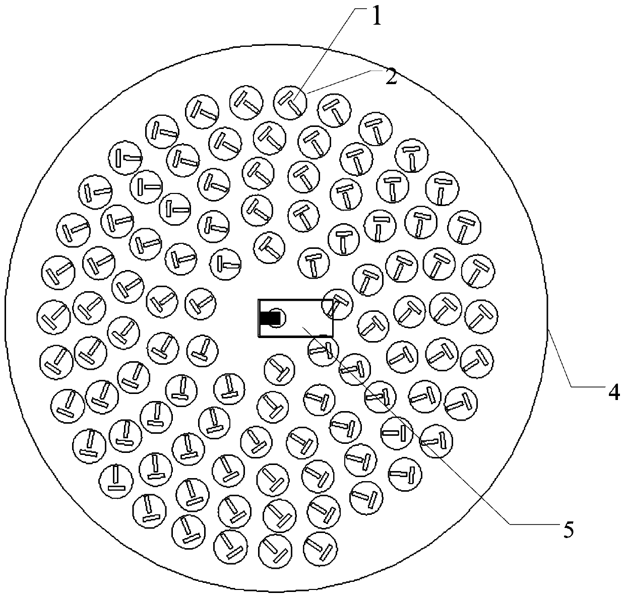
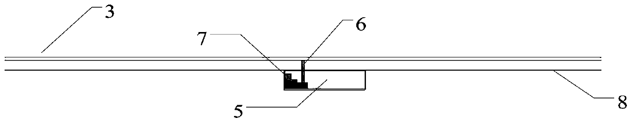
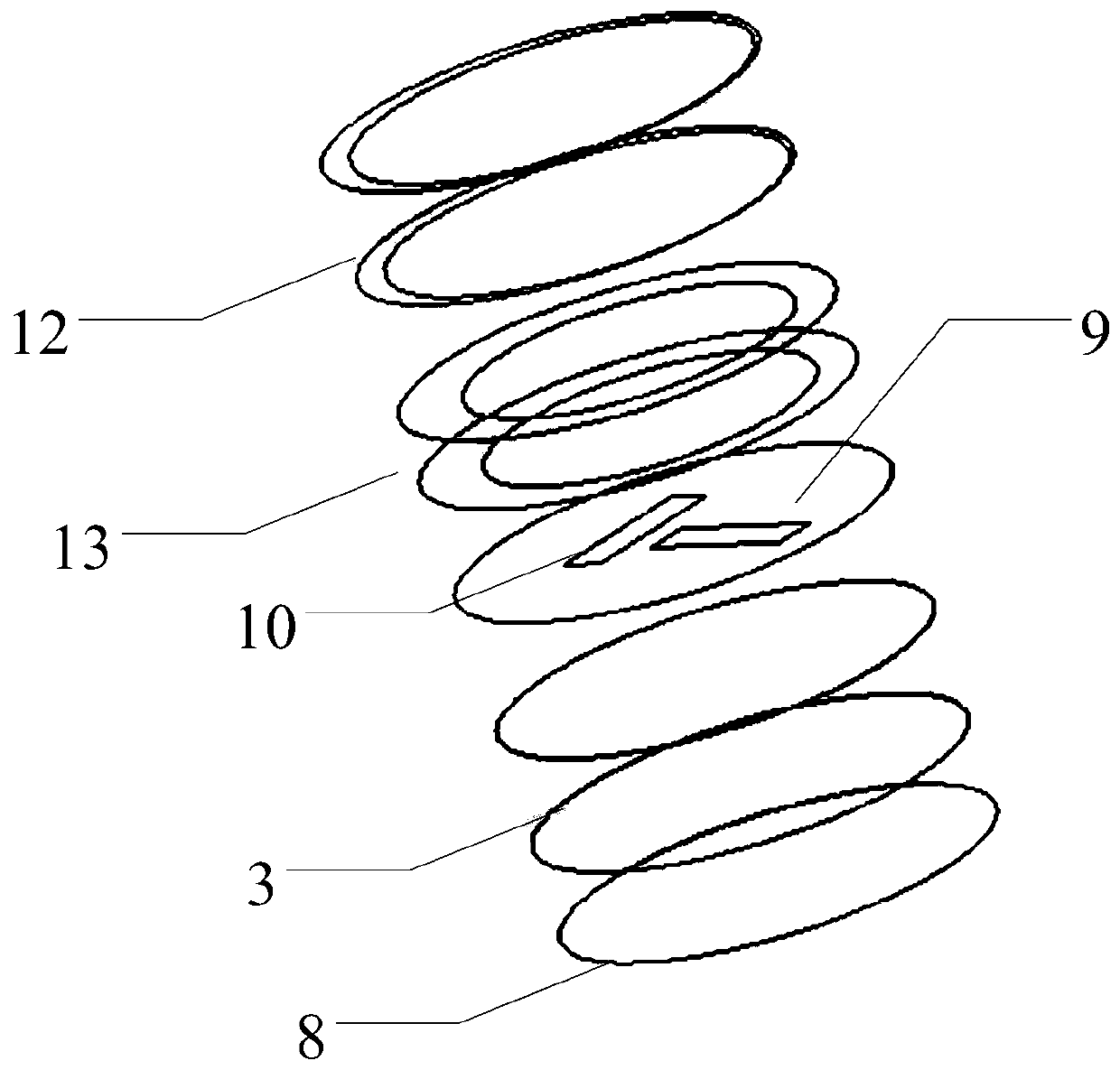
[0035] Such as figure 1 with image 3 As shown, a circularly polarized high-efficiency radial array antenna includes a feed structure 5, a dielectric-loaded radial waveguide 4, and a radiation unit. The radiation unit is a two-order circular waveguide mouth structure loaded with orthogonal slots, including radiation unit 1 in the orthogonal slot layer and radiation unit 2 in the waveguide mouth layer. The orthogonal slot layer radiation unit 1 includes a slot 9 and a slot 10, and the two slots are in an orthogonal relationship. The radiation unit 2 of the waveguide opening layer is a two-stage circular waveguide opening structure, including two-stage waveguide openings: the top waveguide radiation opening 12 and the transition waveguide radiation opening 13 . The edge of the radial waveguide 4 can be used in three ways, open circuit, short circuit, and load absorbing material. Its field distribution is a Hankel function corresponding to the standing wave and traveling wave ...


PUM

PropertyMeasurementUnit
Gap lengthaaaaaaaaaa

Abstract

The invention discloses a circularly polarized high-efficiency radial array antenna. An antenna main body is a dielectric loaded radial waveguide; the antenna comprises a plurality of radiation unitsand a feed structure, the radiation unit comprises an orthogonal slot array loading two-order circular waveguide port structure arranged at one side of the radial waveguide; the distance between the two orthogonal slots is 1 / 4 wavelength, so that the difference between the radiation phases is 90 degrees, and circularly polarized waves are formed; and the two-order circular waveguide port structurecomprises a top-layer waveguide radiation port and a transition waveguide radiation port which are superposed with the orthogonal slot. The orthogonal slot array formed in one side of the radial waveguide is adopted to load the two-order circular waveguide port structure, and compared with a traditional slot, the structure has the advantages that unit gain is improved, wave beams are narrowed, the structural strength of the antenna is improved through a multi-layer structure, coupling between units is reduced, and impedance matching is increased through unit step transition; the radial spacing of the radiation units is a working wavelength lambda g, coupling between the units is reduced, and the efficiency under a large caliber is improved.

Description

technical field [0001] The invention relates to the technical field of antennas, in particular to a circularly polarized high-efficiency radial array antenna. Background technique [0002] In recent years, with the rapid development of radar and satellite communications, the demand for high-efficiency and high-gain antennas has gradually increased. At the same time, circularly polarized antennas are not sensitive to the position of the transmitting and receiving antennas and have high anti-interference capabilities. Traditional microstrip The antenna has the characteristics of low profile and easy realization of circular polarization, but its structural strength is poor and its radiation efficiency is not high. Circularly polarized antennas with traditional waveguide structures have disadvantages such as bulkiness and bulkiness. Therefore, it is of great significance to study a circularly polarized antenna with high efficiency, high gain, high strength and light weight. ...

Claims


Application Information

Patent Timeline
IPC IPC(8): H01Q1/36H01Q1/38H01Q1/50H01Q21/00
CPCH01Q1/36H01Q1/38H01Q1/50H01Q21/00
Inventor 梁一山商远波宋诚夏龙安徐海琴曹捷李政
Owner SHANGHAI RADIO EQUIP RES INST
Why Eureka
Try Eureka