Skin stripping device for wire and cable recycling

A wire and cable and stripping device technology, applied in recycling technology, electronic waste recycling, circuits, etc., can solve the problems of inability to effectively limit the cable, low cable stripping efficiency, and no winding function. Avoid jittery shift effects

Inactive Publication Date: 2020-04-10
桐庐瑶琳永明电线电缆厂
View PDF0 Cites 2 Cited by
  • Summary
  • Abstract
  • Description
  • Claims
  • Application Information

AI Technical Summary

Problems solved by technology

[0003] At present, most of the skin stripping devices for wire and cable recycling on the market have the following deficiencies in the process of use: they do not have the winding function, and they cannot effectively limit the cable. The efficiency is low. In summary, most of the existing stripping devices for wire and cable recycling can not meet the actual needs well.

Method used


Image

  • Skin stripping device for wire and cable recycling
  • Skin stripping device for wire and cable recycling
  • Skin stripping device for wire and cable recycling

Examples


Embodiment 1

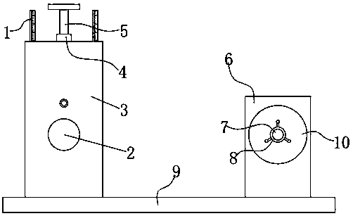
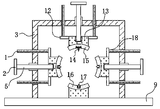
[0026] refer to Figure 1-4 , a skin peeling device for wire and cable recovery, including a base plate 9, three equidistant circularly distributed peeling mechanisms 18 and a winding mechanism, the three peeling mechanisms 18 and the lower arc seat 16 limit the space of the cable, to avoid the cable from peeling When shaking and shifting, the top outer wall of the bottom plate 9 is welded with a U-shaped plate 3, and the outer walls on both sides and the top of the U-shaped plate 3 are provided with round holes and two via holes. Three peeling mechanisms 18 are distributed on the U-shaped plate 3 The two sides and the top of the strip, the peeling mechanism 18 includes a round tube 4, the round tube 4 is welded in the round hole, the inner wall of the round tube 4 is threadedly inserted with a threaded rod 5, the end of the threaded rod 5 is welded with a handle 2, the threaded rod 5. One end away from the handle 2 is connected with a connecting seat 13 through a bearing rota...

Embodiment 2

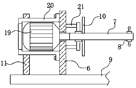
[0035] refer to Figure 5, a skin peeling device for electric wire and cable recovery, the main difference between this embodiment and embodiment 1 is that in this embodiment, the top outer wall of the bottom plate 9 is welded with a support plate 22, and the side wall of the support plate 22 has a fixing hole, The inner wall of the fixing hole is welded with a transverse tube 23, and the transverse tube 23 is located between the U-shaped plate 3 and the winding mechanism.

[0036] When in use, one end of the cable is passed through the horizontal tube 23 and then wound on the winding core. The horizontal tube 23 can guide the cable and reduce the vibration of the cable.


PUM


Abstract

The invention discloses a skin stripping device for wire and cable recycling. The device comprises a bottom plate, three stripping mechanisms which are annularly distributed at equal intervals and a winding mechanism, and the outer wall of the top of the bottom plate is fixedly connected with a U-shaped plate. The outer walls of the two sides and the outer wall of the top of the U-shaped plate areeach provided with a circular hole and two via holes. The three stripping mechanisms are distributed on the two sides and the top of the U-shaped plate. The stripping mechanism comprises a round pipe, the round pipe is fixedly connected into the round hole, a threaded rod is inserted into the inner wall of the round pipe through threads, a grab handle is fixedly connected to the end of the threaded rod, a connecting base is rotatably connected to the end, away from the grab handle, of the threaded rod through a bearing, an arc-shaped groove is formed in the side wall, away from the threaded rod, of the connecting base, and an arc-shaped base is fixedly connected to he inner wall of the arc-shaped groove. According to the skin stripping device for wire and cable recycling, the device can be used for quickly stripping the skin of a long cable, the operation of the device is simple, and the cable stripping efficiency is improved.

Description

technical field [0001] The invention relates to the technical field of skin peeling devices, in particular to a skin peeling device for recycling electric wires and cables. Background technique [0002] Wire and cable, also referred to as cable for short, are mainly used for the transmission of strong electric energy in transmission, distribution, transmission, transformation, and power supply lines, and are also used to transmit electric (magnetic) energy, information and wire products that realize electromagnetic energy conversion. Wires and cables need to be replaced after being used for a long period of time. Waste cables have a certain recycling value. When recycling, it is necessary to glass the skin of waste cables. [0003] At present, most of the skin stripping devices for wire and cable recycling on the market have the following deficiencies in the process of use: they do not have the winding function, and they cannot effectively limit the cable. The efficiency is...

Claims


Application Information

Patent Timeline
Patent Type & Authority Applications(China)
IPC IPC(8): H01B15/00
CPCH01B15/006Y02W30/82
Inventor 余早贵姚春
Owner 桐庐瑶琳永明电线电缆厂
Why Eureka
Try Eureka