
Display device

A display device and liquid crystal display panel technology, applied in the direction of instruments, optics, optical components, etc., can solve the problems of non-orthogonality, light leakage of the liquid crystal display panel, light leakage at the four corners of the display panel, etc., to reduce light leakage, avoid brightness increase, balance abnormal display effect

Active Publication Date: 2020-04-10
XIAMEN TIANMA MICRO ELECTRONICS
View PDF9 Cites 3 Cited by
  • Summary
  • Abstract
  • Description
  • Claims
  • Application Information

AI Technical Summary

Problems solved by technology

However, for the curved liquid crystal display panel prepared by hard bending technology, since the array substrate and the opposite substrate in the liquid crystal display panel are forcibly bent, stress birefringence will occur when the array substrate and the opposite substrate are bent. At the same time, the liquid crystal display panel When the upper and lower polarizers are bent, the polarization states of the transmission axes will not be orthogonal, which will lead to the phenomenon of light leakage in the dark state of the liquid crystal display panel, especially in the edge area of ​​the panel. and serious light leakage around the edges

Method used


Image

  • Display device
  • Display device
  • Display device

Examples


Embodiment Construction

[0020] The present invention will be further described in detail below in conjunction with the accompanying drawings and embodiments. It should be understood that the specific embodiments described here are only used to explain the present invention, but not to limit the present invention. In addition, it should be noted that, for the convenience of description, only some structures related to the present invention are shown in the drawings but not all structures.

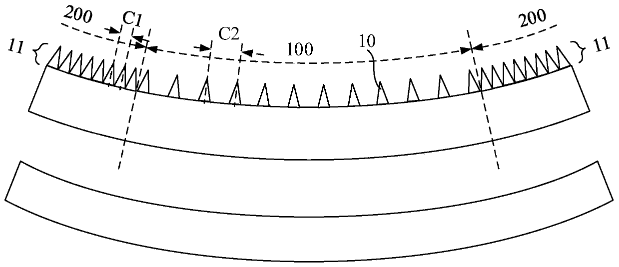
[0021] As mentioned in the background technology section, due to the large bending degree of the edge area of ​​the curved liquid crystal display panel, the birefringence stress of the substrate increases, resulting in more obvious birefringence when the light passes through the substrate, and the light exits more easily. dispersion. At the same time, the upper and lower polarizers of the liquid crystal display panel are bent to a large extent, so that the polarization states of the transmission axes are not ortho...


PUM

PropertyMeasurementUnit
heightaaaaaaaaaa

Abstract

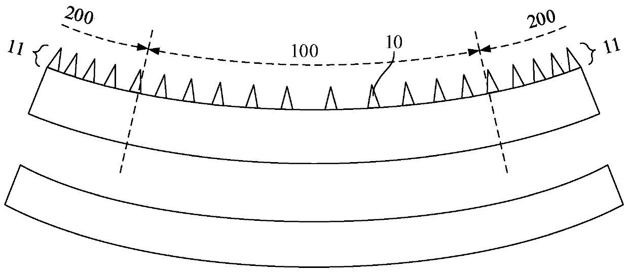
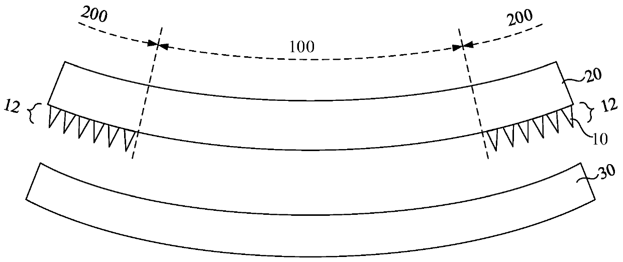
The embodiment of the invention discloses a display device. The display device comprises a first antireflection film and / or a second antireflection film. A plurality of moth-eye microstructures are arranged in the first antireflection film, and the tops of the moth-eye microstructures face the light emitting side of the display device; the first anti-reflection film is arranged in the middle region and the edge region; in the first antireflection film, the arrangement density of the moth-eye microstructures in the edge region is greater than that of the moth-eye microstructures in the middle region. The second anti-reflection film is arranged in the edge region, a plurality of moth-eye microstructures are arranged in the second anti-reflection film, and the tops of the moth-eye microstructures are against the light emitting side of the display device with back. According to the embodiment of the invention, the problem of non-uniform display caused by light leakage and the like around the display device and in the edge area is solved; and abnormal display generated in the edge area can be balanced by reasonably distributing the moth-eye microstructure arrangement density of the first antireflection film; and the light leakage of the edge area is absorbed through the second antireflection film, so that the brightness increase of the edge position caused by the light leakage is avoided.

Description

technical field [0001] Embodiments of the present invention relate to the field of display technologies, and in particular, to a display device. Background technique [0002] When large-sized display panels or display screens are applied to fields such as vehicles, the display panels and display devices are usually designed as curved displays in order to fit with supporting structures. Moreover, with the clear, multi-modal, and diversified development of vehicle-mounted displays, curved surface displays have become a major trend in future vehicles. A curved display panel refers to a display panel with a curved display interface, which may include a flexible display panel prepared on a flexible substrate such as plastic, metal sheet, or glass sheet. [0003] For the liquid crystal display panel, during the preparation process of the curved liquid crystal display panel, the boxed liquid crystal display panel can be hard bent to realize the display effect of the curved surface...

Claims


Application Information

Patent Timeline
Patent Type & Authority Applications(China)
IPC IPC(8): G02F1/1335G02F1/1333G02B1/118
CPCG02F1/1335G02B1/118G02F1/1333G02F1/13356G02F1/133565G02F1/133562
Inventor 方丽婷宋琼
Owner XIAMEN TIANMA MICRO ELECTRONICS
Learn More