
Omnidirectional magneto-optical optical optical pumping magnetometer

An optical pump magnetometer and magneto-optical technology, applied in the field of magnetic measurement, can solve problems such as failure to work normally, performance degradation, disappearance, etc., to achieve the effect of improving application efficiency

Inactive Publication Date: 2020-04-10
SHANDONG INST OF AEROSPACE ELECTRONICS TECH
View PDF9 Cites 7 Cited by
  • Summary
  • Abstract
  • Description
  • Claims
  • Application Information

AI Technical Summary

Problems solved by technology

[0004] Due to the limitation of the working principle of the optical pump magnetometer, the laser polarization direction, the direction of the radio frequency magnetic field and the direction of the measured magnetic field must meet a certain angle relationship to obtain the best magnetic resonance signal. The traditional magneto-optical optical pump magnetometer probe and When the angle of the measured magnetic field is at certain angles, the magnetic resonance signal weakens or even disappears completely, leading to poor steering, reduced detection performance, or even failure to work normally (that is, there is a detection blind zone), which makes the magnetometer of the magneto-optical pump magnetometer on the moving platform There are certain limitations in the application of the magnetometer on the mobile platform, so solving the above-mentioned performance degradation and detection blind zone problems is of great significance for improving the application efficiency of the magneto-optical pump magnetometer on the motion platform

Method used


Image

  • Omnidirectional magneto-optical optical optical pumping magnetometer
  • Omnidirectional magneto-optical optical optical pumping magnetometer
  • Omnidirectional magneto-optical optical optical pumping magnetometer

Examples


Embodiment Construction

[0018] In order to make the object, technical solution and advantages of the present invention clearer, the present invention will be further described in detail below in conjunction with the accompanying drawings.

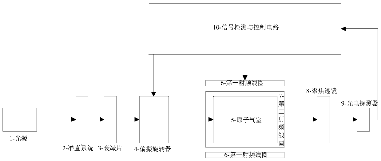
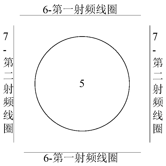
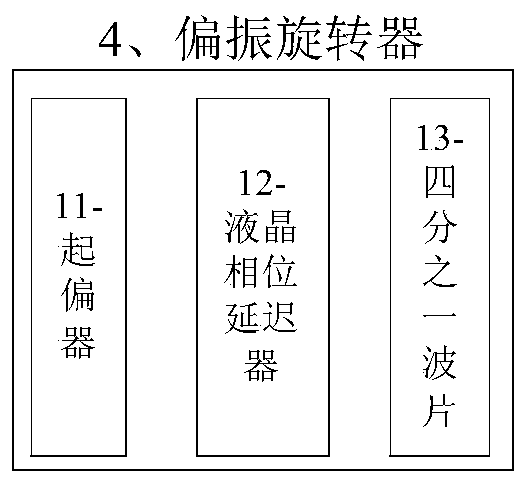
[0019] An omnidirectional magneto-optical optical pump magnetometer sequentially includes: a light source, a collimation system, an attenuation plate, a polarization rotator, an atomic gas chamber assembly (including an atomic gas chamber and two pairs of radio frequency coils), a focusing lens, a photodetector, Signal detection and control circuit.

[0020] The light source 1 is generally a laser light source, such as a semiconductor laser and its temperature control and driving power supply. The wavelength corresponds to the working elements and energy levels of the atomic gas chamber, and should be kept accurate and stable. Generally, it should have a special frequency stabilization system.

[0021] The collimation system 2 shapes and collimates the laser light...


PUM


Abstract

The invention relates to an omnidirectional magneto-optic optical pump magnetometer which comprises a light source, a collimation system, an atomic gas chamber, a focusing lens and a photoelectric detector which are arranged in sequence. The invention also comprises a polarization rotator arranged between the collimation system and the atomic gas chamber; the polarization4 rotator is used for rotating the polarization direction of the light beam; two pairs of radio frequency coils are wrapped outside the atomic gas chamber, and the two pairs of radio frequency coils are intersected; the lightbeam entering the atomic gas chamber generates optical pumping and magnetic resonance effects under the action of the atomic gas chamber and the magnetic field of the radio frequency coil to form a magnetic resonance signal; and the signal detection and control circuit converts an optical signal of the photoelectric detector into a feedback signal and transmits the feedback signal to the radio frequency coil and the polarization rotator. The magneto-optical optical pumping magnetometer has the beneficial effects that the detection performance of the magnetometer is improved, the problems of detection blind areas and the like are solved, and the application efficiency of the magneto-optical pumping magnetometer on a motion platform is improved.

Description

technical field [0001] The invention belongs to the field of magnetic measurement technology, and in particular relates to an omnidirectional magneto-optical optical pump magnetometer. Background technique [0002] Optically pumped magnetometer is a weak magnetic sensor based on quantum optical effects such as Zeeman effect, optical pumping effect and magnetic resonance. It has the characteristics of high sensitivity, high precision and small temperature drift. Navigation, communication, target detection and human magnetic field detection and other fields. [0003] According to the difference of the magnetic resonance mechanism, the optical pump magnetometer can be divided into an all-optical optical pump magnetometer and a magneto-optical double-resonance optical pump magnetometer. instrument), that is, the magnetic resonance signal is acquired through laser pumping and radio frequency magnetic field. [0004] Due to the limitation of the working principle of the optical ...

Claims


Application Information

Patent Timeline
IPC IPC(8): G01R33/26
CPCG01R33/26
Inventor 邵思霈任文冠宋晓林史钰峰时洪宇
Owner SHANDONG INST OF AEROSPACE ELECTRONICS TECH
Learn More